

An interesting question was raised in the 1950s by the mathematician Ernst Straus: In an arbitrarily shaped empty room with side walls made of perfect mirrors, will a point light source always illuminate the whole room? This question was answered elegantly by the Nobel laureate Sir Roger Penrose, who designed a room with unilluminable areas that is thus termed “the Penrose unilluminable room”. However, is the Penrose unilluminable room really unilluminable? Using the COMSOL Multiphysics® software to generate simulations, we will see if this is the case and discuss the fundamental assumption of ray optics.
The Illumination Problem
When you hear the question for the first time, it might not be immediately clear what exactly it is asking. Let’s consider the example shown in the figure below. As shown on the left, the mirrored side wall of a 2D room can take an arbitrary shape, and the light source can be placed in any location within the room. In this particular case, it’s easy to imagine that the whole room will be illuminated by the light source, which is unsurprisingly confirmed by the ray tracing simulation on the right. Essentially, Straus’ question is whether there exists a design of the shape of the room such that, when a point light source is placed inside, certain areas are not illuminated.
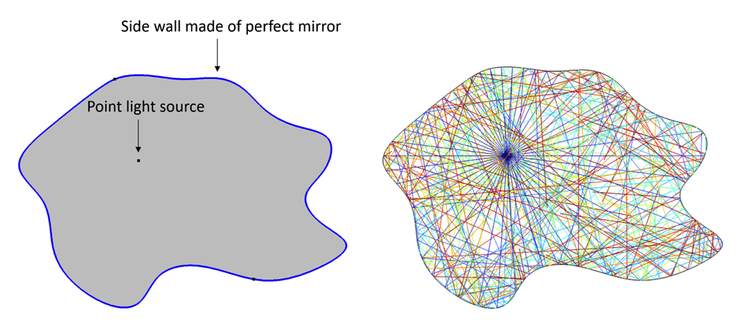
An empty room with arbitrarily shaped side walls made of perfect mirrors and a point light source inside the room (left). A ray tracing simulation showing that the entire room is illuminated by the point light source (right).
Upon seeing the problem, I immediately thought that perhaps a room with very sharp corners could prevent certain areas from being illuminated. You have probably already guessed it, however: If it were this easy to figure out the shape of an unilluminable room, it wouldn’t have been an interesting question for the science community. We can see that, given sufficient time, the light will always illuminate the whole room. At this point, you might not be convinced and think you can design an unilluminable room. If you are up to the challenge, please feel free to use the Ray Optics Module to give it a try!
A room with sharp corners fully illuminated by a point light source.
The Penrose Unilluminable Room
This tricky problem was ultimately tackled by the brilliant Roger Penrose, winner of the 2020 Nobel Prize in Physics. His design, shown in the figure below, is not obvious at all at first glance. The room consists of two elliptical walls on the top and bottom and a rectangular area with two “umbrella” cutouts. The only requirements for the design to work are that the top and bottom walls are described as an ellipse x^2/a^2+y^2/b^2=1 and that the focal points of the ellipse coincide with the corner points of the “umbrellas”. Details such as the specific values of a and b, the shape of the umbrella, the width of the umbrella, and so on won’t change the property of the room.
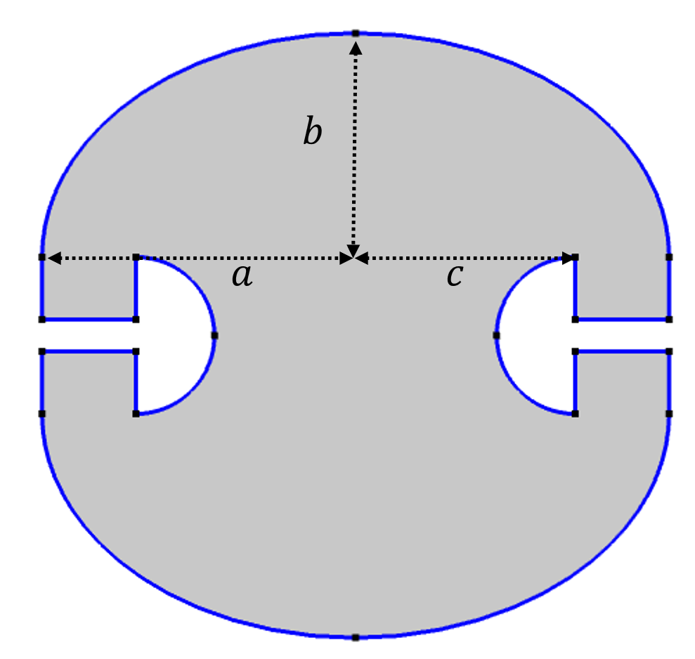
The design of the Penrose unilluminable room.
Let’s use the Ray Optics Module to see if it works! In the animations below, we placed the point light source at some representative points — in the center, in the top half, and to the left of the left-hand umbrella (“underneath” the umbrella, if we imagined it were upright). Light rays are launched from the point isotropically. Clearly, in every case, there are areas not illuminated by the light. When the light source is placed “underneath” the umbrella, the light doesn’t even travel to the lower half of the room. Note that this is not because the time-domain simulation has not been run for long enough. Even when time approaches infinity, these shadow areas remain unilluminated.
Ray tracing simulations with the point light source placed in different locations of the Penrose unilluminable room. In all cases, there always exist areas not illuminated.
The special characteristics of the Penrose unilluminable room come from the special properties of the elliptical mirror. You may recall from your college optics class that light originating from one focal point of an elliptical mirror will be focused on the other focal point. This property is demonstrated by the animation below on the left. The other lesser known property of an elliptical mirror is that when the light originates between a focal point and the closest apex of the ellipse, it will only arrive at a point between the other focal point and the other apex, never intersecting the long axis between the focal points. This property is demonstrated by the animation in the middle below. In addition, light originating between the two focal points will never intersect the long axis between each focal point and its closest apex, as demonstrated by the animation on the right.
Left: Light rays launched at a focal point will only intersect the long axis at the focal points. Middle: Light rays launched between a focal point and the closest apex will not intersect the long axis between the focal points. Right: Light rays launched between two focal points will only intersect the long axis between the focal points.
With these properties in mind, we can divide the Penrose unilluminable room into the regions shown below. It’s important to note again that in Penrose’s design, the focal points of the ellipse coincide with the edges of the umbrellas. As such, we know that:
- A light source placed inside A_1 will only illuminate A_1, B_1, and A_2 because it can never intersect the long axis of the ellipse between the focal points and enter the C_1 area.
- A light source placed in B_1 will leave A_3 and A_4 unilluminated because the light rays can only enter the lower half of the room between the two focal points of the lower ellipse. Thus, they can never intersect the long axis between the focal points and apexes and enter A_3 and A_4.
- A light source placed in C_1 will leave A_1, A_2, A_3, and A_4 unilluminated for the same reason.
Due to the symmetry, the same effects will occur for a light source placed in the corresponding regions of the lower half of the room. Therefore, we can conclude that the Penrose unilluminable room will always have unilluminated areas no matter where the point light source is placed within the room.
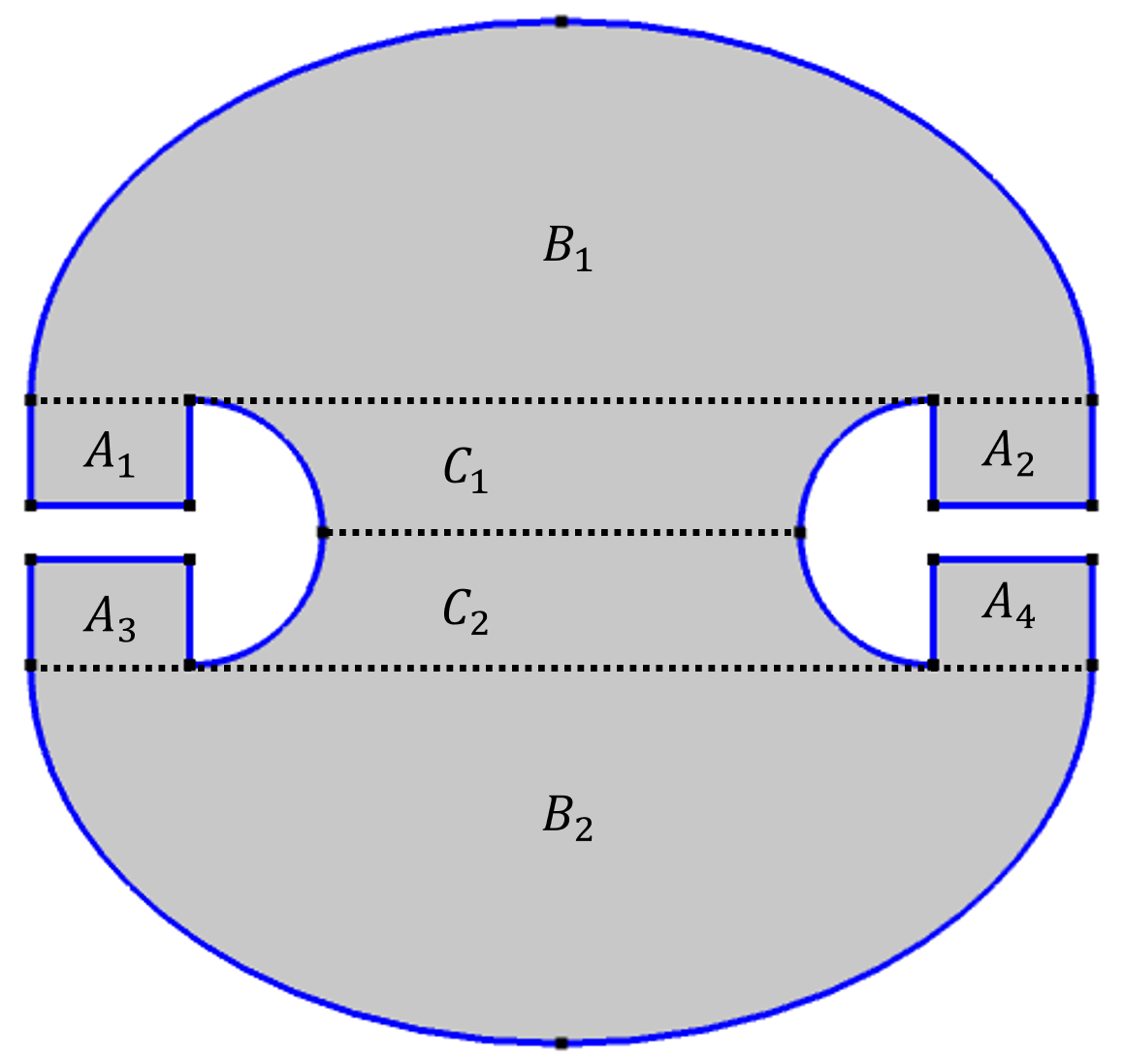
Dividing the room into different regions. A light source placed inside A_1 will only illuminate A_1, B_1, and A_2. A light source placed in B_1 will leave A_3 and A_4 unilluminated. A light source placed in C_1 will leave A_1, A_2, A_3, and A_4 unilluminated.
Let There Be Light: Illuminate the Unilluminable Area
The ray tracing simulations above seem to show convincing results that confirm the room being unilluminable, but is it really? We need to remember the fundamental assumption of ray optics: that the wavelength of the light is much smaller than the size of the object that the light interacts with, so that the diffraction effect can be totally ignored. Recall a is the long axis of the ellipse that describes the top and bottom walls of the room. The ray optics simulation essentially assumes the wavelength 𝜆<<𝑎 . If we have a real life room whose dimension is in the order of meters and a light source in the visible spectral range (~500 nm wavelength), this assumption holds up very well. But what if we shrink the room or increase the wavelength of the light such that \lambda is comparable to a?
To test this, we switch to the Wave Optics Module to perform full wave simulations. A point Line Current (Out-of-Plane) is placed “underneath” the umbrella in the top left corner (in the A_1 region), similar to the third ray tracing animation of the room shown above. The Line Current functions as a point source that emits a cylindrical wave with the electric field pointing in the out-of-plane direction. The field distributions at increasing wavelengths are simulated in the frequency domain and shown below. At \lambda=a/40 (top left), the field distribution is similar to the ray tracing simulation, as expected. The field does not seem to penetrate the lower half of the room. However, as the wavelength gets longer, diffraction becomes more prominent, such that the field leaks into the lower half of the room. At \lambda=a/10 (bottom left) and \lambda=a/5 (bottom right), it’s very clear that the previously unilluminated area is illuminated!
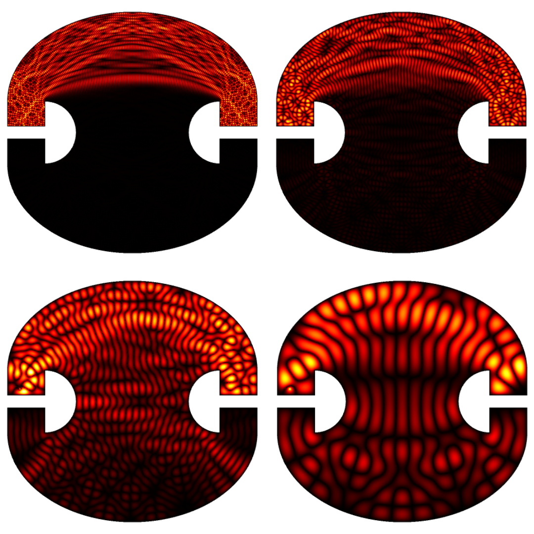
Simulated field distributions in the frequency domain at \lambda=a/40, \lambda=a/20, \lambda=a/10, and \lambda=a/5. At shorter wavelengths, the field distribution resembles the ray tracing result. However, at longer wavelengths, the field penetrates into the area that was previously not illuminated due to diffraction. The norm of the electric field is plotted in these figures.
In addition to using the Electromagnetic Waves, Frequency Domain interface to visualize the field distribution at equilibrium, running a time-domain simulation using the Electromagnetic Wave, Transient interface can help to visualize the wave propagation and diffraction.
Out-of-plane electric field emitted by a Line Current located in the top half of the room “underneath” (to the left of) the left-hand umbrella and simulated in the time domain. Due to diffraction, the field leaks into the lower half of the room. The wavelength is a/5.
Wave Interference
So far, our simulations seem to suggest that the Penrose unilluminable room is only unilluminable under the assumption that the diffraction effect can be totally ignored. However, we must realize that we can’t jump to this conclusion so quickly. The situation is actually more complicated. When the wave nature of the light emerges, another important phenomenon — interference — needs to be taken into account. By looking at the frequency-domain simulation results, we can see that in many areas, the norm of the electric field is in fact zero. This is because the outgoing wave and the diffracted wave interfere and form a standing wave pattern with nodes of zero field intensity. Therefore, in a sense, those areas are not illuminated at equilibrium. There will always be areas with no light if we wait long enough. On the other hand, we can think about it in the time domain. When the light wave propagates into these areas for the first time, they are illuminated for a period of time, until the diffracted wave arrives to cancel the electric field. In this sense, the whole room is illuminated, at least for certain period of time. In conclusion, whether the whole room is unilluminated or not depends on your interpretation. Most importantly, we can see that, at different scales, an optical phenomenon can look drastically different. As simulation practitioners, we always need to keep in mind the fundamental difference between wave optics and ray optics, as well as the unique phenomena associated with them.
Final Thoughts
Besides the fact that this mathematical brainteaser is interesting, the Penrose unilluminable room is an excellent example to demonstrate the fundamental difference between wave optics and ray optics. Under different assumptions, the conclusion to the same question can be totally different. It also answers a question that we get a lot from beginners: The COMSOL® software has two optics modules. Which one, the Wave Optics Module or the Ray Optics Module, should I use to simulate my optics problem? The short answer is: If we are concerned with geometries whose size is orders of magnitude larger than the relevant wavelength, e.g., visible light interacting with camera lens systems or lidar operating on the street, using the Ray Optics Module is perfectly fine. On the other hand, if we are interested in light scattering of nanoparticles whose size is smaller or comparable to the wavelength, full wave simulation with the Wave Optics Module or the RF Module is inevitable. At the same time, the choice of the module also depends on which physical quantities and processes you are interested in. For example, ray optics simulation yields light propagation paths while wave optics simulation can render the full electric field distribution.
Choosing the appropriate module for your simulation not only ensures the accuracy of your simulation result but also can save you a tremendous amount of simulation time.
Next Step
Try the Penrose Unilluminable Room model yourself by clicking the button below, which will take you to the Application Gallery entry:
Further Resources
- Want to learn more about this illumination problem? Check out these videos, which discuss the Penrose unilluminable room in depth using animations, drawings, and a 3D printer:

Comments (0)