Optimizing the Interference Fit Between 2 Pipes with Structural Analyses

The interference fit between two parts has to be just right. Think of it as the Goldilocks quandary of structural mechanics: if the fit is too loose, the parts won’t hold together; if it’s too tight, the parts can’t join. For optimal performance of a structure involving joined parts, the interference fit needs to be calculated. One method is to create a simulation app, which can efficiently compute the contact pressure and surface displacement of two joined parts.
Finding an Interference Fit that Is “Just Right”
In an interference fit, also known as a press fit, two parts are joined together with minimal space in between. Initially, the inner object has a slightly larger diameter than the outer one. The outer part is heated until it is large enough to fit the inner part. After the inner part is inserted, the outer object shrinks over it during cooling, which strengthens the fastening. A suboptimal interference fit can cause the parts to come loose, bulge excessively because of permanent plastic deformations, or make it impossible for the parts to fit together. However, with the right interference fit, the parts essentially fuse into one piece that can be held together, even when met with a large amount of torque.
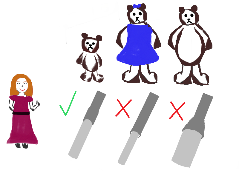
A new take on the popular Goldilocks fairy tale: Instead of a bowl of porridge heated to her preferred temperature, Goldilocks finds an interference fit for two pipes that is neither too tight nor too loose.
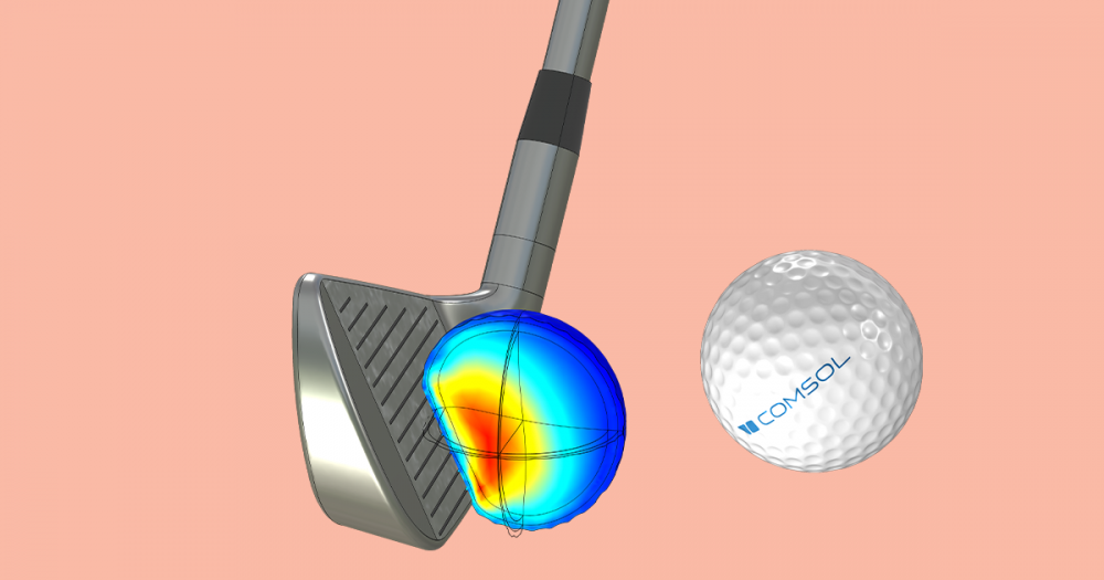
An optimized interference fit reduces unwanted effects in a structure. For instance, in ball bearing assemblies, the interference fit protects against the bearing sliding on the shaft. If the interference fit is too loose, sliding will still occur, but if it is too tight, the ball bearing will experience increased operation temperature and wear particles.
For the best performance of a structure, the interference fit needs to be optimized with the application in mind. By building a simulation app, it is possible to efficiently evaluate parameters that affect the interference fit between two parts.
Calculating Interference Fit with a Simulation App
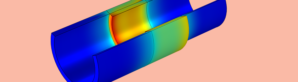
The Interference Fit Calculator computes and visualizes the interference fit between two pipes. The app includes an Input section where app users can enter different geometry parameters to quickly and easily test designs.

In this example, the inputs include:
- Outer diameter of the outer pipe, inner diameter of the inner pipe, and common diameter
- Radial interference fit
- Contact length
- Friction coefficient
The user-friendly interface of the app makes it easy to compute and visualize the results of the interference fit analysis. You can include buttons such as Solve, Reset to Default, Create Report, and Open Documentation for app users to run and view different analyses.
The different Results tabs of the app enable you to visualize how slight parameter changes affect the interference fit, which are computed by the underlying model. The results show the maximum transferable torque and axial force, as well as the equivalent stress, contact pressure, and pipe deformation for different inputs.
The Interference Fit Calculator is an example of what you can create with the Application Builder, a built-in tool included with the COMSOL Multiphysics® software. As you are in control of an app’s design, you can include different inputs and outputs to suit your needs.
The Interference Fit Calculator in action.
With a simulation app, you can test different parameters to optimize the interference fit for your specific structural application.
Next Steps
Click the button below to try the Interference Fit Calculator example.
- Learn about analyzing stress in threaded pipe geometries on the COMSOL Blog
- Download a tutorial model on studying the interference fit connection in a mountain bike fork
- Explore the Structural Mechanics Module


Comments (0)