
Microfluidic systems often rely on valveless pumps, as they are both gentle on the biological material and low in the risk of clogging. However, by design, this type of pump is not suitable for viscous fluids and systems with small length scales or low flow rates. To overcome this limitation, you can introduce a micropump mechanism that converts oscillatory fluid motion into a unidirectional net flow.
What Is a Valveless Micropump?
Miniature devices have many applications and researchers are constantly finding new uses for them. One such use, which we’ve blogged about before, is a microfluidic device that could let patients conduct immune detection tests by themselves. But to work in the microscale, devices like this one, of course, rely on even smaller components such as micropumps.
Let’s turn to a model of a valveless micropump mechanism that was created by Veryst Engineering, LLC using the COMSOL Multiphysics® software.
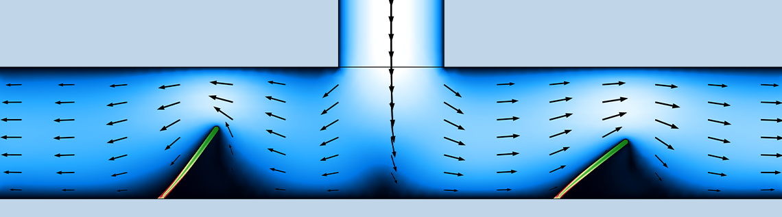
The micropump in the tutorial model creates an oscillatory fluid flow by repeating an upstroke and downstroke motion. The fluid flow enters a horizontal channel containing two tilted microflaps, which are located on either side of the micropump. The microflaps passively bend in reaction to the motion of the fluid and help to generate a net flow that moves in one direction. Through this process, the micropump mechanism is able to create fluid flow without the need for valves.
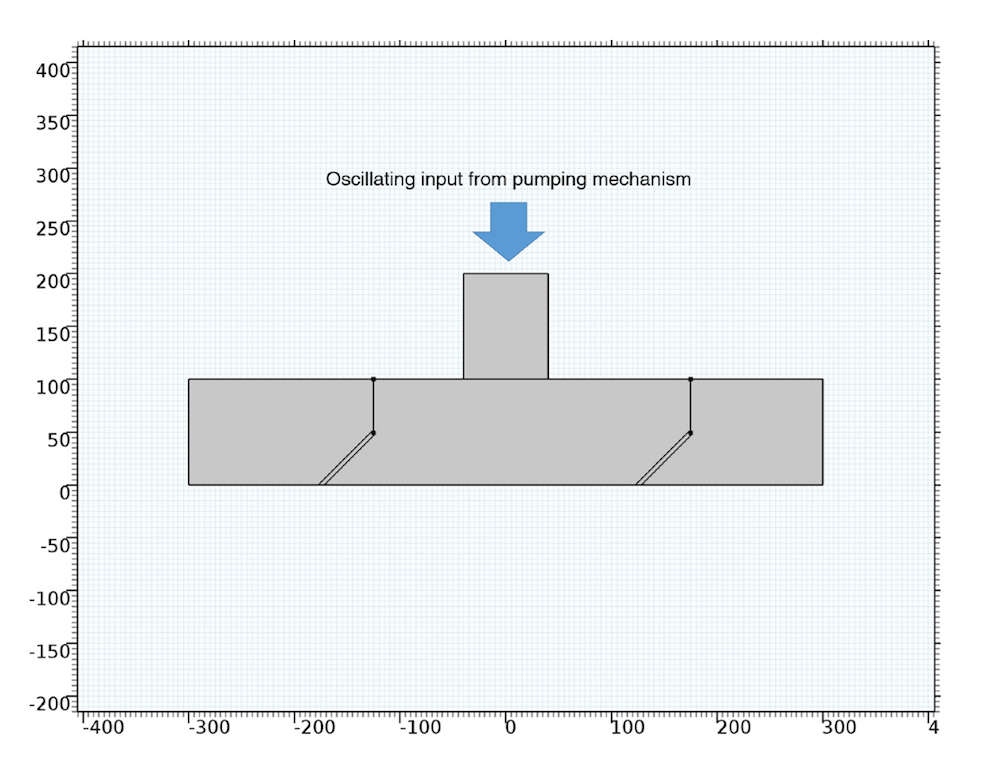
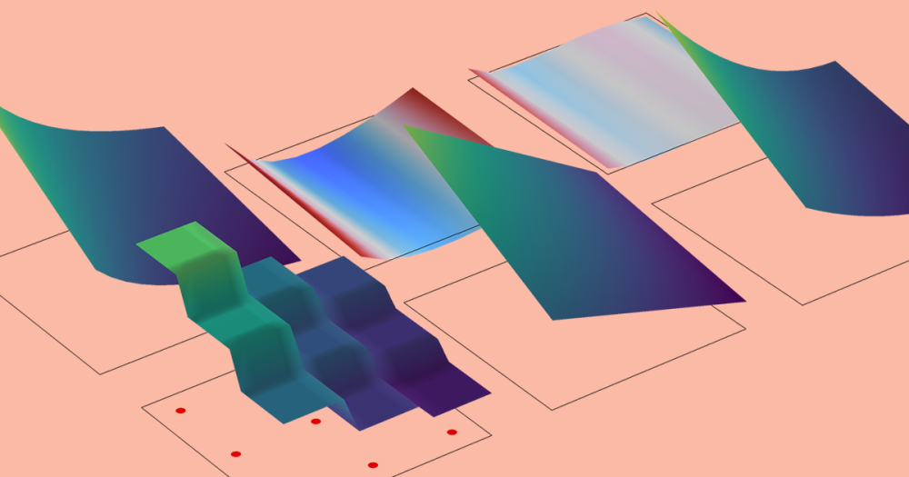
The geometry of the micropump mechanism tutorial.
Please note that the straight lines above the microflaps are there to help the meshing algorithm. Check out the model documentation if you’d like to learn how this model was created.
Evaluating the Micropump’s Performance with Simulation
The model calculates the micropump mechanism’s net flow rate over a time period of two seconds — the amount of time it takes for two full pumping cycles. The Reynolds number is set to 16 for this simulation so that we can evaluate the valveless micropump mechanism’s performance at low Reynolds numbers. The Fluid-Structure Interaction interface in COMSOL Multiphysics is instrumental in taking into account the flaps’ effects on the overall flow, as well as making it an easy model to set up.
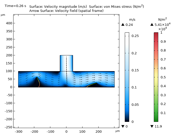
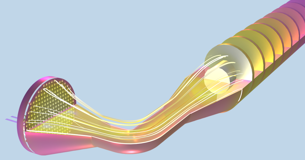
At a time of 0.26 seconds, the fluid is pushed down and most of it flows to the outlet on the right.
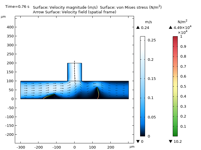
At a time of 0.76 seconds, the fluid is pulled up and most of it flows from the inlet on the left.
The simulation starts with the micropump’s downstroke, which is when the micropump pushes fluid down into the horizontal channel. This action causes the microflap on the right to bend down and the microflap on the left to curve up. In this position, the left-side microflap is obstructing the flow to the left and the flow channel on the right is widened. This naturally causes the majority of the fluid to flow to the right, since it is the path of least resistance.
During the following pumping upstroke, fluid is pumped up into the vertical chamber. Here, the flow causes the microflaps to bend in opposite directions from the previous case. This shift doesn’t change the direction of the net flow, because now the majority of the fluid is drawn into the flow channel from the inlet on the left.
Due to the natural deformation of the microflaps caused by the moving fluid, both of these stages created a left-to-right net flow rate. But how well did the micropump mechanism do at maintaining this flow over the entire simulation time period?
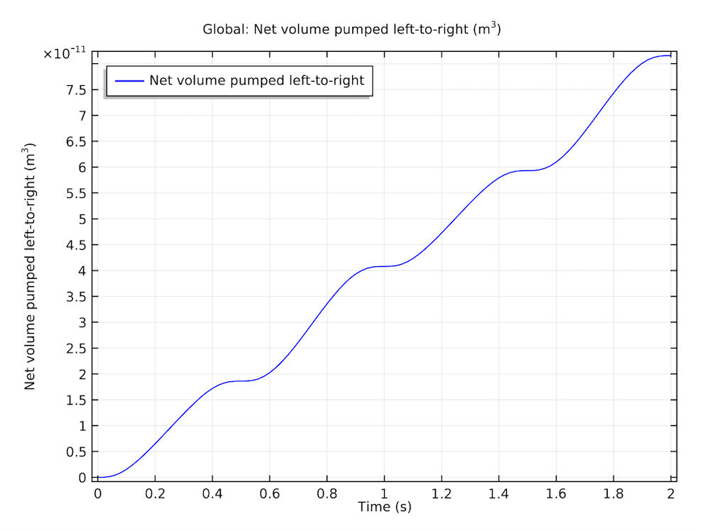
The net fluid volume that is pumped from left to right.
During the two-second test, the net volume pumped from left to right was continually increased, with a higher net flow rate during peaks of the stroke speed. This valveless micropump mechanism can function even at a lower Reynolds number.
The valveless micropump mechanism could have many future applications, one of which is to work as a fluid delivery system. In such a scenario, a micropump mechanism could take fluid from a droplet reservoir on its left and move it through a microfluidic channel to an outlet on its right. In this post we have shown just one set of simulation results. By experimenting with the tutorial model set up by Veryst Engineering, you can visualize how a valveless micropump may work in different situations and use this information to discover new uses for micropump mechanisms.
Editor’s note: This blog post was updated on August 25, 2023, to include new versions of the model images. The previous version of the blog post featured model images produced with COMSOL Multiphysics version 5.1.


Comments (0)