

How does thermal contact resistance affect heat transfer? As the sizes of electronic devices continue to decrease, effective heat management becomes even more important. Today, electronic packaging has transitioned from its original purpose of providing mechanical protection and interconnection to also serving as a means of heat dissipation to the outside environment. Using a model from the Model Gallery, we explore the role of thermal contact resistance on heat management in a simple electronic package and heat sink assembly.
What Is Thermal Contact Resistance?
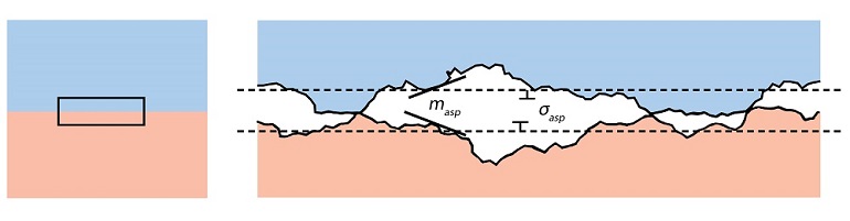
Heat transfer will take place when materials at different temperatures come into contact with one another. It may initially appear that the surface of each material is entirely in direct contact. However, upon closer inspection, you’ll find that many materials have a surface roughness measurable at the micron or nanometer scale.
When materials are in direct contact, thermal conductivity is determined by the properties of the two materials. However, surface roughness introduces gaps between contacting materials, which are usually filled with air. The thermal conductivity of gasses, such as air, is typically much lower than the conductivity of common solid materials. Therefore, the heat flux due to conduction is smaller in noncontacting regions, leading to increased thermal resistance at the interface.
Yet, if you increase the structural stress over the gap, you’re going to decrease the size and extent of the gaps and, therefore, influence the thermal resistance. Most of the time, there is also surface-to-surface radiation in the gap, however, it can be neglected in many common applications as the temperature difference between the materials is usually sufficiently small.
Thermal Contact Resistance in an Electronics Example
In the Model Gallery, you can find the pre-solved model “Thermal Contact Resistance Between an Electronic Package and a Heat Sink“, which can be used to investigate the effect of thermal contact resistance on heat transfer in an electronic package.
The model is based off of a study by M. Grujicic, C.L. Zhao, and E.C. Dusel of Clemson University titled “The effect of thermal contact resistance on heat management in the electronic packaging“. In their paper, the authors use finite element analysis (FEA) to investigate the effect that thermal contact resistance has on heat management in a simple central processing unit (CPU) and heat sink design. They explore the effect of surface roughness, the mechanical and thermal properties of the contacting materials, the contact pressure, and the effect of the materials on the maximum temperature experienced by the CPU in detail in their paper.
In the COMSOL Multiphysics model, part of the Grujicic et al. study is reproduced, where we take a look at the influence of four main parameters on thermal contact resistance, and, thereby, the heat transfer:
- Contact pressure
- Microhardness
- Surface roughness
- Surface roughness slope
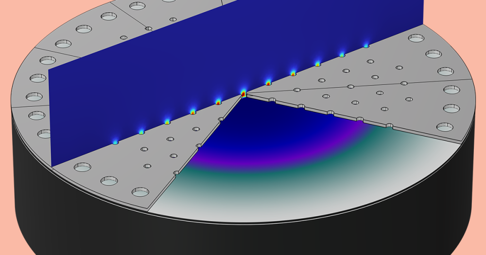
The model geometry is composed of a cylindrical electronic package that is located inside a heat sink constructed of eight cooling fins. Device efficiency is dependent on the eight cooling fins of the heat sink, as well as on the efficiency of heat transfer between the electronic package and heat sink. The device geometry is shown below, where radial symmetry has been used to reduce the geometry to one sixteenth of its original size.
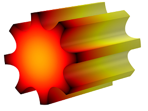
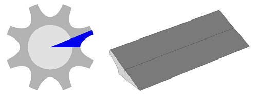
Left: Heat sink and electronic package geometry, showing the eight cooling fins around the cylindrical package. Middle and right: Radial symmetry and simplification of the geometry.
The electronic package is modeled as a cylinder with a radius of 1 centimeter and a height of 5 centimeters and is made of silicon. The heat sink is made of aluminum with fins reaching a distance of 2 centimeters from the cylinder axis. The electronic package produces a total heat source of 5 W. In order to dissipate this heat, a cooling fan blows room-temperature air at 8.5 m/s across the heat sink.
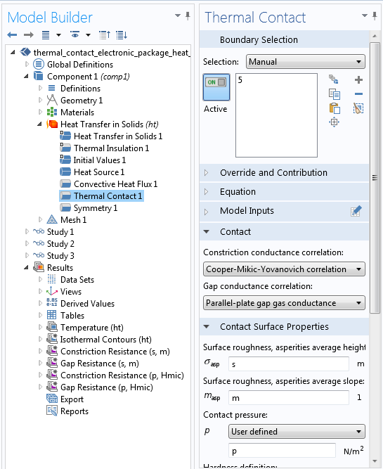
To define the cooling due to the air flow, we use the built-in heat transfer coefficient in COMSOL Multiphysics. The four parameters — contact pressure, microhardness, surface roughness, and surface slope — can all be modeled using parametric sweeps set up in the Thermal Contact interface. Both a free triangular mesh and a swept mesh are used in the model.
Tip: You can find more information about the mesh in the model documentation.
The figure below shows the temperature profile obtained using reference values:
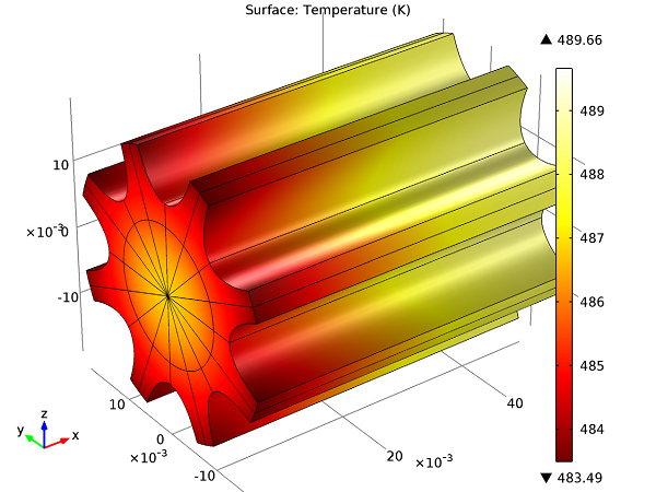
Temperature profile with reference values for the parameters.
Closer to the fan (on the left side of the model), the temperature of the fins reaches about 483 K. The temperature increases with greater distance from the fan, reaching 490 K at the other extremity.
Analyzing Constriction Resistance and Gap Resistance
Next, we further analyze the model to determine the effect of contact pressure, microhardness, surface roughness, and surface slope on constriction and gap resistance within the model. The amount that each of these four parameters affect both the constriction resistance and gap resistance directly influences the material characteristics at the surface of the heat sink and electronic packaging. Thus, the heat dissipation from the electronic device is altered.
Below are the results from this analysis:
")
")
Left: Constriction resistance depending on contact pressure (x-axis) and microhardness (y-axis). Right: Constriction resistance depending on roughness (x-axis) and roughness slope (y-axis).
")
")
Left: Gap resistance depending on contact pressure (x-axis) and microhardness (y-axis). Right: Gap resistance depending on roughness (x-axis) and roughness slope (y-axis).
Contact pressure, roughness, roughness slope, and microhardness all affect the constriction resistance within the model. However, roughness slope has little to no effect on the gap resistance. We can see this in the bottom-right image, where the plot shows constant values in the vertical direction.
In their paper, Grujicic et al. make the conclusion that surface roughness and mechanical and thermal properties can have a significant effect on thermal contact resistance, and, therefore, on thermal management. According to Grujicic et al., thermal contact resistance, and the parameters that influence it, can play a major role in the heat management of electronic devices. Therefore, it may significantly affect device performance, reliability, and life cycle.
Additional Resources
- Read the paper: “The Effect of Thermal Resistance on Heat Management in the Electronic Packaging” by M. Grujicic, C.L. Zhao, and E.C. Dusel
- Download the model: Thermal Contact Resistance Between an Electronic Package and a Heat Sink


Comments (1)
Somil Joshi
July 19, 2022I need demonstration on this