Subsurface Flow Module Updates
For users of the Subsurface Flow Module, COMSOL Multiphysics® version 5.3 brings three new boundary conditions: Well, Interior Wall, and Thin Barrier. Read about these Subsurface Flow Module features below.
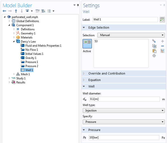
New Well Boundary Condition
The Darcy's Law, Richards Equations, and Two-Phase Darcy's Law interfaces now include an option to model wells more easily. The new Well boundary condition makes it possible to select edges in 3D or points in 2D, where either injection wells or production wells are active. Settings for the Well feature include entering the well diameter, choosing the well type, and specifying an injection pressure or mass flux.
Saturation after 365 days in a 5-spot injection pattern (1/4 symmetry) modeled using the Two-Phase Darcy's Law interface with anisotropic material properties. An injection well is located at the upper-right corner and the production well at the lower-left corner of the square.
New Interior Wall Boundary Condition
The Darcy's Law, Richards Equations, and Two-Phase Darcy's Law interfaces can now define thin interior walls. The Interior Wall feature is useful to avoid meshing thin impermeable structures embedded in porous media, such as retaining walls, plates, slabs, etc., thus reducing computational time and resources.
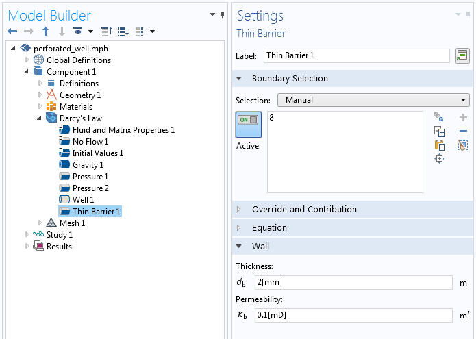
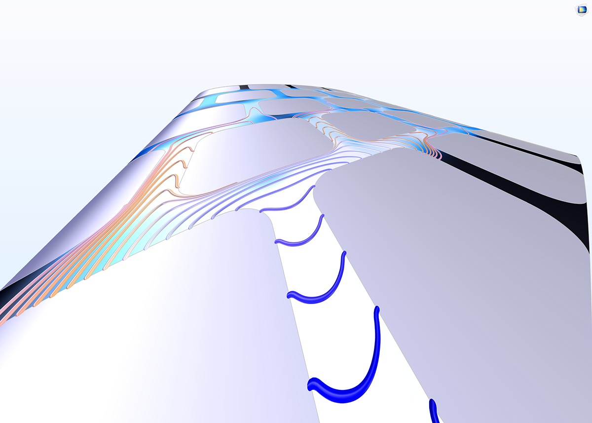
New Thin Barrier Boundary Condition
In the Darcy's Law and Richards Equations interfaces, you can now define permeable walls on interior boundaries with the Thin Barrier boundary condition. These internal boundaries are typically used to represent thin, low permeability structures. With the Thin Barrier boundary condition, you avoid meshing thin structures like geotextiles or perforated plates, thus reducing computational time and resources.
New Transport of Diluted Species in Fractures Interface
Fractures have thicknesses that are very small compared to their length and width dimensions. It is often difficult to model the transport of chemical species in such fractures through having to mesh the thickness of the fracture surface, due to the aspect ratios brought about by the large differences in size dimensions. The new Transport of Diluted Species in Fractures interface treats the fracture as a shell, where only the transverse dimensions are meshed as a surface mesh.
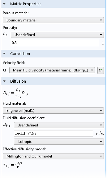
The interface allows you to define the average fracture thickness, as well as the porosity in cases where the fracture is considered to be a porous structure. For the transport of the chemical species, the interface allows definition of effective diffusivity models to include the effects of porosity. Convective transport can be coupled to a Thin-Film Flow interface or through including your own equations to define fluid flow through the fracture. Additionally, chemical reactions can be defined to occur within the fractures, at its surfaces, or in a porous medium that encompasses the fracture.
 Transport of diluted species along a slightly curved fracture surface. The curved surface consists of an imprinted tortuous path through the surface where flow and chemical species transport occur.
Fracture Surfaces in the Transport of Diluted Species in Porous Media Interface
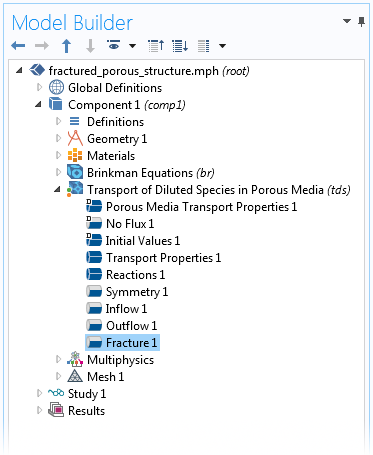
In cases where transport occurs in a fractured, porous 3D structure, the new Fracture boundary condition lets you model transport in the thin fractures without having to mesh them as 3D entities. The Fracture boundary condition is included in the Transport of Diluted Species in Porous Media interface (see image) and has the same settings as in the Transport of Diluted Species in Fractures interface (described above). Fluid flow and chemical species transport are seamlessly coupled between a 3D porous media structure and fluid flow and chemical species transport in a fracture.
The image below shows the concentration field in a porous reactor model. In the model, a twisted fracture "leaks" reactants deeper into the porous catalyst, from left to right, at a faster rate than the transport through the porous media. This is because the fracture surface has a much higher average porosity compared to the surrounding porous catalyst, which gives a higher mass transport rate.
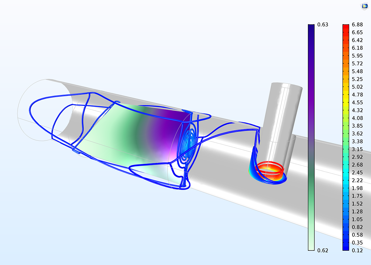 Concentration contours through the 3D reactor and surface concentration in the fracture surface. The higher mass transport rate in the fracture surface gives a larger penetration (from right to left) of unreacted species into the catalyst bed. We can see that the change in concentration from right to left is very small in the fracture surface (from 0.63 to 0.62 mol/m3)