
Whenever solid materials are heated enough, they will melt and then vaporize to a gas. Certain materials will even go directly from the solid to the gas phase, a process referred to as sublimation or ablation. If the material is heated strongly enough, there will be significant material removal. Today, we will look at how you can model this process in COMSOL Multiphysics.
Material Removal by Ablation
As a solid material is heated, its temperature will rise and it will eventually undergo a phase transition. This transition can involve either going to the liquid phase and then to the gas phase or going directly to the gas phase. For our purposes, we will consider only those materials that go directly to the gas phase.
Let’s further assume in this case that the material is being heated in such a way that the maximum temperature develops on the surface and that there is no internal heating that might lead to an internal gas-filled void within the solid. Thus, we limit ourselves to situations where sublimation occurs at the surface. We can also assume that once the material transitions to the gas phase, it is no longer thermally significant. This is a reasonable assumption whenever there is some kind of additional surrounding gas flow that carries the vaporized material away. The process of heating the surface of a material to the gaseous state and quickly removing the gas from the vicinity of the solid is often called ablation.
Ablation requires a large heat flux to be delivered to the surface of the material. One of the most practical examples of such a heat source is a laser. This approach is applied to a range of processes, including laser machining, surgical procedures, and laser engraving, among others. The heat source, of course, does not necessarily need to be a laser. In fact, ablative heat shields have been used to help spacecraft survive the high heat loads experienced during atmospheric reentry.
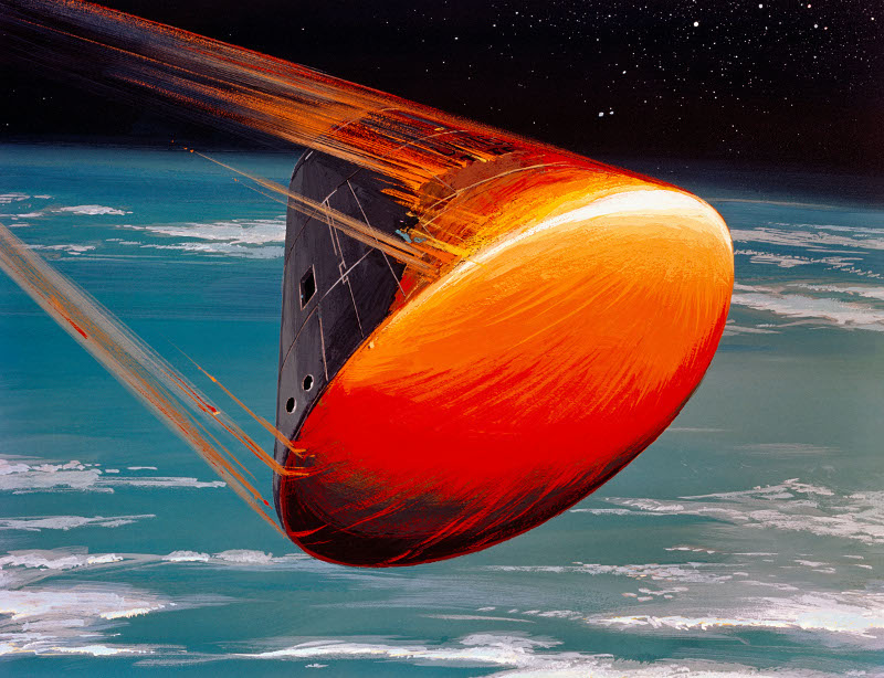
An artist’s rendition of a heat shield on a reentry vehicle.
Modeling ablation requires setting up and solving a model that computes the temperature variation in a solid material over time, while also including the heat of sublimation and the resultant material removal. First, we must develop a thermal boundary condition that enforces the condition that the solid material cannot exceed the sublimation temperature. Second, we need to develop a method for modeling the mass removal from the domain of interest. Let’s see how we can accomplish these tasks in COMSOL Multiphysics.
Modeling Thermal Ablation in COMSOL Multiphysics
To begin, we’ll consider a highly simplified model of the heat shield on the spacecraft shown above. We will assume that the heat flux across the heat shield is uniform in time and space. Another assumption we make is that the material properties of the heat shield are constant and that there are negligible temperature gradients in the plane of the shield as compared to through the thickness. Under these assumptions, we can reduce our model to a one-dimensional domain, as illustrated below.
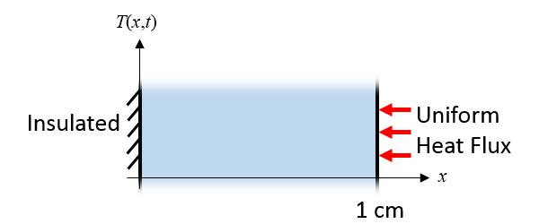
A heat shield (as pictured earlier) with a uniform heat flux can be reduced to a 1D model.
Our thermal boundary conditions for the 1D domain begin with the thermal insulation condition at one side, meaning that there is no removal of heat through the spacecraft body. At the other side, there is a uniform constant heat flux that approximates the effect of atmospheric heating during reentry.
Lastly, we need to include a set of boundary conditions that model the heat loss due to material ablation. As the material reaches its ablation temperature, it changes its state to a gas and is removed from our modeling domain. Therefore, the solid material cannot become hotter than the ablation temperature, and when the material is at its ablation temperature, there is a loss of mass from the surface that is governed by the material density and the heat of sublimation. To model this element, we will need both a thermal boundary condition and a way to model the material removal.
The thermal boundary condition that we will introduce to model ablation is an ablative heat flux condition of the form:
(1)
where q_a is the heat flux due to material ablation, T_a is the ablation temperature, and h_a=h_a(T) is a temperature-dependent heat transfer coefficient that is zero for T < T_a and increases linearly as T > T_a.
The slope of this curve is very steep, enforcing that the temperature of the solid cannot markedly exceed the ablation temperature. In addition to the thermal boundary condition, we must also include the material removal. The rate at which the solid boundary is eroded is:
(2)
where v_a is the material ablation velocity, \rho is the material density, and H_s is the heat of sublimation.
Let’s now look at how these equations are implemented in COMSOL Multiphysics, starting with the material properties and heat load, as defined via the Global Parameters shown below.
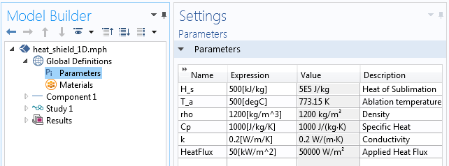
The Global Parameters applied to our 1D model.
Next, the Ramp function is used to define the temperature-dependent heat transfer coefficient needed in Equation (1), as illustrated in the following screenshot. The slope itself is arbitrary, but too small of a value will cause the ablation temperature to be exceeded and too large of a value will cause slow numerical convergence.
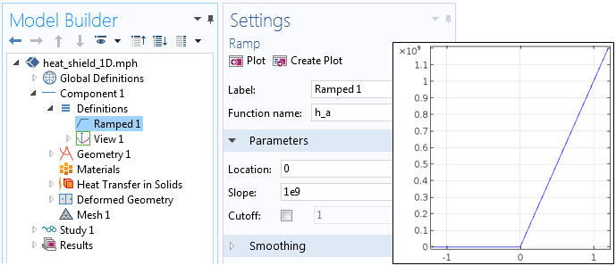
The Ramp function has a very steep slope.
Our model consists of a 1D domain that is 1 cm long. The Heat Transfer in Solids interface is used to model the temperature evolution over time. The incident heat flux is applied at one side and the thermal insulation condition is applied at the other side. The ablative heat flux of Equation (1) is implemented as shown in the screenshot below. Since heat flux conditions contribute, it is the sum of the incident heat flux and the ablative heat flux that is applied to the boundary.
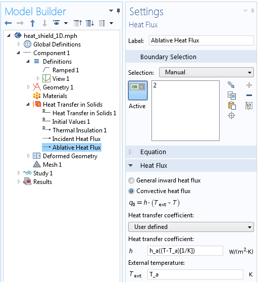
The implementation of the ablative heat flux condition from Equation (1).
To model the material removal, the Deformed Geometry interface is used. The Free Deformation feature allows the domain to change in size, as prescribed by the boundary conditions. On one side (the insulated side), a prescribed deformation enforces no displacement of the boundary. On the other end of the domain, the Prescribed Normal Mesh Velocity condition enforces Equation (2), the material removal rate, as depicted below.
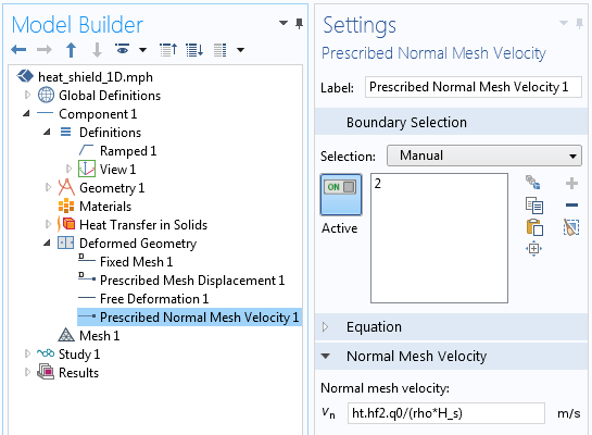
The implementation of the material removal in Equation (2), using the Deformed Geometry interface.
The mesh velocity is given by the expression ht.hf2.q0/(rho*H_s), where ht.hf2.q0 is the heat flux computed via the Ablative Heat Flux boundary condition that was earlier defined. You can always find the definitions of all such internally defined COMSOL variables by going to Results > Reports > Complete Report.
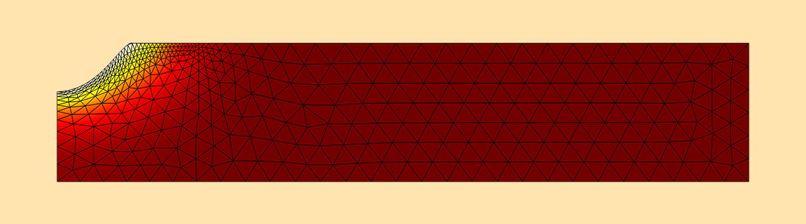
With those features, we have included the effect of ablation and can solve our model for the temperature evolution over time, as plotted below. We can observe that the temperature at the right side of the solid rises up to the ablation temperature and the material starts to become removed from the domain. As the material is ablated, the temperature at the boundary is maintained. Additionally, note that the derivative of the temperature, with respect to position, changes once the material starts to ablate, indicating that the total heat flux has changed.
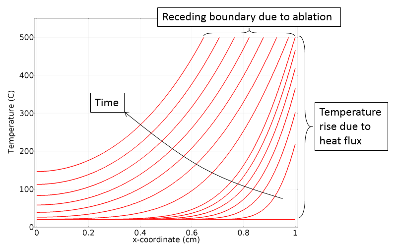
The temperature evolution over time in the 1D domain.
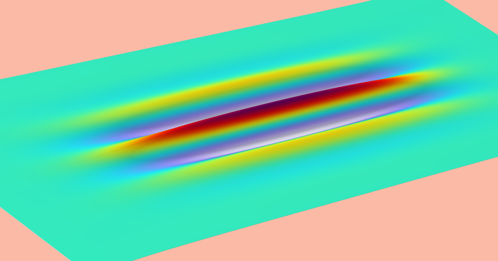
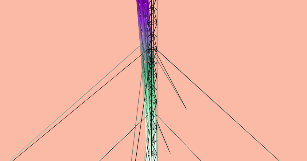
Let’s finish up our discussion by showing the results from a somewhat more complicated problem. The problem involves an axisymmetric geometry with a heat load that has a Gaussian intensity profile. Our focus is simulating laser heating and ablating the material to machine a hole. We can use the exact same model setup as described above, but on a 2D domain.
The simulation results, highlighted in the following animation, show the hole forming over time. The domain change is significant so, in this example, the Deformed Geometry interface uses a Hyperelastic smoothing type to deform the mesh. Note that the Deformed Geometry interface does not admit any topological changes to the domain. Therefore, we cannot model the formation of a through-hole, only the material removal from one side of the modeling domain.
An animation showing laser ablation in a 2D axisymmetric model.
Closing Remarks on Modeling Thermal Ablation
In today’s blog post, we have demonstrated how to use a Heat Flux boundary condition and the Deformed Geometry interface with the Prescribed Mesh Velocity feature to model ablation of a material. The example presented has been kept as simple as possible to focus only on the modeling of ablation. A more realistic model would also include radiative heat transfer from the surface and temperature-dependent material properties.
Further, it is possible to consider a pulsed heat load, a common element in laser machining. To learn more about modeling such cases, please have a look at this earlier blog entry. When heating with a laser, it is also possible for the light to be penetrated some finite distance into the material. In such a case, you may be able to use the Beer-Lambert law to model the energy deposition, among other methods for modeling the laser heating of materials.
If the material itself first undergoes some chemical changes during the heating, we encourage you to read through our previous blog post on the modeling of thermal curing. You can also consider ablation of a thin thermally insignificant layer by following a different approach of introducing an additional equation to track the material damage.
If you’re interested in modeling thermal ablation with COMSOL Multiphysics or have any other questions regarding these topics, please don’t hesitate to contact us.


Comments (43)
Shashank Sharma
April 9, 2016This seems an interesting approach to model laser matter interaction, i have one question though, the temperature dependent ablative heat transfer coefficient has very high values, also in laser modelling the values of heat fluxes are very high which might result in very high mesh velocity which can impede the simulation, secondly can we get acceptable relation of h_a with T in literature ?
your blogs are always helpful, thanks .
shelan.khasro@ilps.uobaghdad.edu.iq khasro
May 31, 2016this model is not available in Application Gallery, how can i get this model ? please
Caty Fairclough
June 1, 2016Hello,
Thank you both for your comments and interest in this blog post!
For your questions, please contact our support team.
Online support center: https://www.comsol.com/support
Email: support@comsol.com
Best,
Caty
shelan.khasro@ilps.uobaghdad.edu.iq khasro
June 1, 2016thank you Caty Fairclough ,i’ll try to contact them.
shelan.khasro@ilps.uobaghdad.edu.iq khasro
June 9, 2016Good morning ,
I am really interested in modeling thermal ablation with COMSOL Multiphysics Kindly would any one send me theis model (Material Removal by Ablation) because it is not available in application gallery.
thank you
浩 杨
August 8, 2016Are there any differences of setup between 1D domain and 2D domain? I can’t make it about the simulation of the animation in the blog (some Inverted mesh always exists) . Could you please give me some information. Thank you!
Bridget Cunningham
August 8, 2016Hello,
Thank you for your comment.
For questions related to your modeling, please contact our support team.
Online support center: https://www.comsol.com/support
Email: support@comsol.com
Best,
Bridget
ashkan razmara
September 3, 2016ashkan razmara
September 3, 2016I need the animation model of laser ablation in this page . Please send me the details ,I couldnt carry it ou
ashkan razmara
September 3, 2016I need the animation model of laser ablation in this page . Please send me the details ,I couldnt carry it out
Ahmad Gad
October 21, 2016Can I get the mph file as I am seeking such a similar simulation?
Thanks and best
a.gaad2@gmail.com
Caty Fairclough
November 3, 2016Hi Ashkan and Ahmad,
Thank you for your comments and for your interest in this blog post! For your requests, I would suggest reaching out to our support team.
Online support center: https://www.comsol.com/support
Email: support@comsol.com
Best,
Caty
naomi posadas
January 9, 2017Can I get the mph file as I am seeking such a similar simulation?
elianeposadas@gmail.com
Thanks and best
Caty Fairclough
January 20, 2017Hi Naomi,
Thanks for your comment and interest in this blog post! For your request, I would suggest contacting our support team.
Online support center: https://www.comsol.com/support
Email: support@comsol.com
Best,
Caty
Vagelis Kalos
March 30, 2017Hello ! Thank you for this tutorial ! But I stil don’t understand how I can solve the Inverse problem. I want to enter only the Laser’s and material’s parameters and compute the temperature on the material’s surface. In your tutorial the ablation temperature is given at the first place.
Thank you very much !
Vagelis
cebo ntuli
August 20, 2017I’ve applied all the conditions. My 2D model converges. However, no material removal is occurring. Please assist.
cebo ntuli
August 20, 2017my e-mail address is cebo.ntuli@gmail.com. Can someone assist me with an mph file of a 2D model.
Seyedpayam Vahdati
November 14, 2017Dear Walter,
I have two questions about the equations. why did you use q0 in equation 1 in equation 2. what are these two q0 represent? I think the q0 in equation 2 represent the extra heat which contribute to ablation (correct?). how is that q0 in equation 1 represent this extra heat?
how do you find the right value for ha in equation 1. is there any formula to calculate it. how do you suggest to do it?
Kind regards
Payam
ht.hf2.q0
Caty Fairclough
December 1, 2017Hi Cebo and Seyedpayam,
Thanks for your comments and interest in this blog post.
For your questions, please contact our Support team.
Online Support Center: https://www.comsol.com/support
Email: support@comsol.com
cebo ntuli
December 7, 2017Dear Caty Fairclough
Thank you for the assistance. I managed to access the tutorial.
Much appreciated.
Regards
Cebo Ntuli
Zhengliang Su
June 14, 2018Hi Walter,
Is that possible to model the formation of a through hole in the same case?
Thanks,
Zhengliang
Walter Frei
June 15, 2018Dear Zhengliang,
Topological changes, such as through hole formation, are not possible by this technique, no.
Best,
Lyubo
July 19, 2020Hello Mr. Frei,
I did the tutorial, but I somehow want to texture the part which is about to be ablated. The geometry is hard to do. I tried with suares that i rotate at 45 degree so I can have a textured surface of the 2D model, without much success.
Second question – only the Ramped function is ablating. I tried with gaussian and triangle without success.
And the ramped function works fast when I cut off at 1.
Best,
Lyubo
Lyubo
July 19, 2020Mr. Frei one more thing – only the 2D axisymmetric ablates at r=0. If I move the ramped function position to outher place, it does not change the ablation process. Also when I use with the same conditions only the 2D there is no ablation.
Ali Kadivar
January 30, 2019Dear Walter,
Following your answer to Zhengliang, could you please let us know how can we model an ablation with topological changes. imagine if this model was in the another rectangle of air.
Sooraj S
February 26, 2019Could anyone please tell the replacement for ht.hf2.q0 term in a 2D model
Richard Boutilier
October 18, 2019It’s the same as in the 1D model.
Jan Carag
July 19, 2019Dear Walter,
Thank you for the blog post, I found the information extremely helpful in furthering my understanding of heat transfer models. I am very interested in how you modeled the process in 2D, however I do not have access to COMSOL 5.4 and cannot access the included application files. Would it be possible to upload the same application files, but for COMSOL 5.3?
Best regards,
Vincent
Richard Boutilier
October 18, 2019I noticed that the geometry of the laser machining model consists of only a single rectangle (no additional points or lines), yet somehow an edge was generated in it’s interior that was used in the selection of the mesh control edge. If anyone knows how this is done, please let me know.
Richard Boutilier
October 21, 2019Update: For anyone else that has this question, the answer is to specify the rectangle has two layers, with the first being 1 [cm] thick from the left.
Youssef Aider
February 26, 2020Great tutorial, I have a question about the case where there is another domain attached to our main ablative material. in this case we cannot add an ablative heat flux but only a boundary heat source. is there a way to account for the ablation heat source in this case? i there a way to make the mesh move and leave the temperature behind? so the heat loss will be automatically accounted for?
thank you
Walter Frei
February 26, 2020 COMSOL EmployeeHello Youssef,
One of the assumptions here is:
“We can also assume that once the material transitions to the gas phase, it is no longer thermally significant. This is a reasonable assumption whenever there is some kind of additional surrounding gas flow that carries the vaporized material away. The process of heating the surface of a material to the gaseous state and quickly removing the gas from the vicinity of the solid is often called ablation.”
That is, this discussion is limited to the case where there is no material (in any state of matter) adjacent to the ablated material. Although what you’re describing should be possible to do, it does get to a different, and more complicated, case that isn’t addressed here.
Lyubo
June 24, 2020Hi,
I want to do laser ablation test on textured surface with ablatant taking the shape of the texture. I also want to measure the force of the plasma and it’s directions when the ablation occures. Can that be achieved? How can I texture the surface?
Walter Frei
July 13, 2020 COMSOL EmployeeDear Lyubo,
The question of modeling the plasma above the surface is indeed quite a bit more complex of a question, and a bit outside of the scope of what this technique is meant to address. We would suggest contacting your COMSOL Technical Support Team with this question.
Victor Martorelli
July 15, 2020Hello, I am new in using COMSOL so this query might be trivial for more experienced users. I need to make the ablation on a specific size for the laser I am using but when I edit the geometry, the ablation seems to break down the whole object. I checked the insulation and boundaries but I believe that the mesh gets altered and the grating is even, unlike the example where where the ablation occurs, it seems more condensed. I am not sure how to make it back so that it turns out like the tutorial specifies.
This blog is really helpful and I would like to thank you for it.
Walter Frei
July 20, 2020 COMSOL EmployeeHello Victor,
This seems like a question that would have to be addressed via support (https://www.comsol.com/support) and in the context of a specific model file (https://www.comsol.com/support/knowledgebase/1098)
Lyubo
July 20, 2020Mr. Frei,
How can the thermal ablation model in 2D Axisymmetric be replaced by laser ablation? Replacing the Ramped function with Gaussian or triangle didn’t help me much. Didn’t melt the material.
Hardik Vaghasiya
August 27, 2020Dear Walter,
Instead of boundary heat flux, if I have domain heat source than how should I ablate material based on this model? In this modeling, If we do not have the value of the temperature-dependent ablative heat transfer coefficient (h_a). Though it is an arbitrary value (h_a), how should we find out the value of h_a?
Moreover, Instead of this, Can we use an element filter method where we can remove element which reaches the vaporization temperature?
Thanks and regards,
Hardik
Harsh Goel
October 28, 2020Great tutorial sir. I want to know if the same technique would work on a 3D model? Actually I tried to incorporate this in Silicon wafer model but nothing was ablating there.
Rushabh Zambad
February 4, 2021Hello,
I would like to model material removal due to wear. Could you send me this model and some tutorials?
Walter Frei
February 4, 2021 COMSOL EmployeeHello Rushabh,
Wear-based material removal is quite different, but is also possible, and is demonstrated in this example: https://www.comsol.com/model/disc-brake-pad-wear-89961
Happy Modeling!
Bob Davis
April 9, 2021Hello
Thanks for this post
For the two-dimensional model that you did beautifully, you used the symmetrical two-dimensional model. I will be warned about an asymmetric two-dimensional or three-dimensional model by following your model.How to simulate an asymmetric two-dimensional model. can you guide me? Also, how can this be considered multi-layered in this model?
Hasan Ilker Celiker
September 5, 2023I want to work the same way on a 3D part, but I can’t get results. It keeps giving me errors. How can we apply it on a 3D part?