Geometry Updates
COMSOL Multiphysics® version 6.0 brings several geometry improvements, including faster build of a previously built geometry node, Group nodes in the Model Builder, and Offset and Thicken operations now also available in 2D. Browse all of the geometry updates below.
Faster Build of a Previously Built Geometry Node
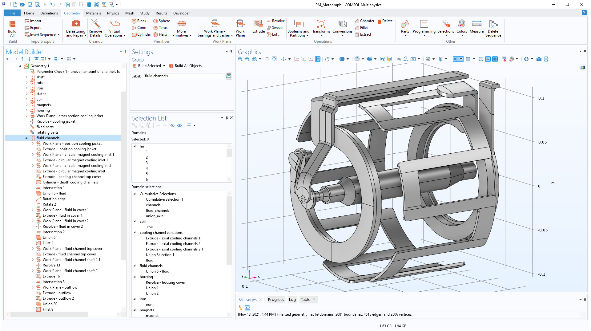
In COMSOL Multiphysics® version 6.0, building the geometry corresponding to any feature in a previously built geometry sequence is significantly faster than before, due to improved caching. This makes it very quick to display the geometry in a state corresponding to a feature, even for a long sequence of operations.
When setting up this permanent magnet motor, improved caching makes it faster to build any previously built Geometry node in a long geometry sequence.
Group Nodes in the Model Builder
You can now add Group nodes to the geometry sequence to organize the feature nodes. The Group nodes act like folders that you can expand, collapse, and add feature nodes to. The geometry features are still built from top to bottom in the order they appear in the model tree. You can use group nodes to structure long sequences, where you do not need to instantiate parts of the geometry, and for which you can use geometry parts instead.
Rotate About an Edge or Vertex
In the Rotate operation, you can now rotate about a selected straight edge in 3D or a selected vertex in 2D. This new functionality is in addition to the previously available options to enter coordinates for the axis of rotation, or Euler angles.

Mirror in an Edge
For 2D geometries, the Mirror operation has a new option for specifying the line of reflection by selecting a straight edge. This makes it easier to mirror objects in a sketch where you also want to use the constraints and dimension functionality available with the Design Module.

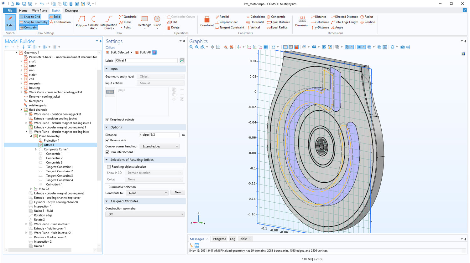
Construction Geometry
You can now designate the output of any geometry feature in 2D and 3D as Construction geometry, to be used to help with creating other geometry objects. In sketch mode, construction geometry is displayed with dashed lines, and the construction objects on a work plane are not carried over to the 3D sequence. For example, to convert a line into a construction geometry object, simply right-click the line and select Construction Geometry from the menu. The construction objects are not included in the finalized geometry either. You can use construction geometry, for example, in a 3D sequence to create sketches that you constrain and dimension, leveraging existing objects by using Cross Section or Projection features.

Offset and Thicken 2D Curves
For 2D geometry sequences, the new Offset operation offsets the edges of an input object at a given distance in the normal direction. The new Thicken operation creates a solid object by thickening the edges of the input curve object in the normal direction.
Extract Entities From Geometry Objects
The new Extract operation creates a new object from a selection of entities. All other entities will be deleted or kept in a remainder object. You can also use the Extract feature on a selection of objects to delete all the other objects. This is useful when the number of objects or entities you would like to keep is a lot less than the number of objects you would like to delete.
The Extract operation with the Input object handling property set to Remove is used when creating this bike frame geometry to keep only the domains needed after partitioning the intersecting tube sections. This workflow can be faster compared to selecting all the small domains that should be deleted after the partitioning, and it can also be more robust if the frame geometry needs to be parameterized, since the number of small domains after partitioning may depend on the dimensions.
List of Named Selections
You can now get an overview of all named selections for the current geometric entity level in the Selection List window, which can be found by selecting the Windows button on the Home tab. The named selections are listed below the list of entities, and include the selections under the Definitions node and those created in the geometry or the mesh sequences. You can click a selection from the list to view the entities in the selection highlighted in the Graphics window, and in the list of entities. You can also right-click a selection, and from the menu choose to hide or show the entities in the selection, or to add or remove them from the active input selection list of a feature.
