Rotordynamics Module Updates
For users of the Rotordynamics Module, COMSOL Multiphysics® version 6.0 brings a new Solid Rotor, Fixed Frame interface, liquid annular seal functionality, and turbulence and surface roughness effects for hydrodynamic thrust bearings. Read about these and more updates below.
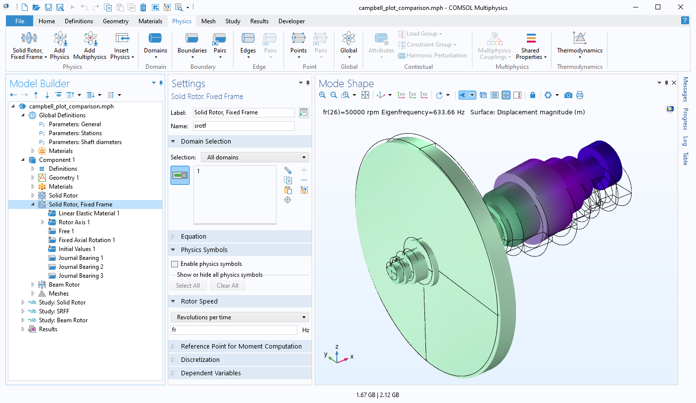
Solid Rotor, Fixed Frame Interface
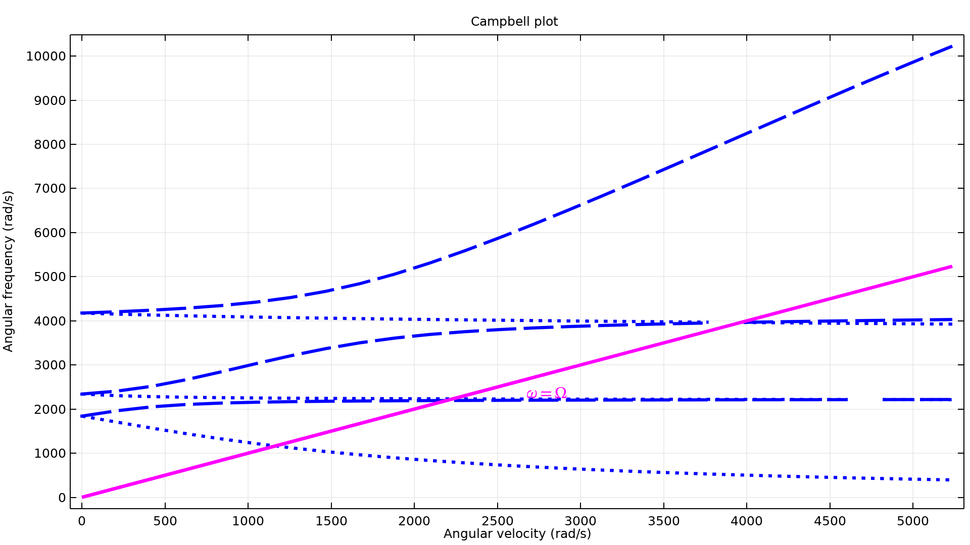
A new physics interface called Solid Rotor, Fixed Frame can be used to model axially symmetric rotors using a 3D geometry in space-fixed frames. This interface essentially has the same functionality as the existing Solid Rotor interface but one advantage of the new interface is that it does not require special transformation of the variables from a corotating frame to a space-fixed frame to interpret the results. In particular, the Campbell plot is directly obtained in the space-fixed frame, hence it does not suffer from the problems with the transformation of the eigenfrequencies encountered in a solid rotor model due to wrong detection of the whirling modes. You can see this new interface in the Comparison of Campbell Plots Using Different Rotor Interfaces tutorial model.
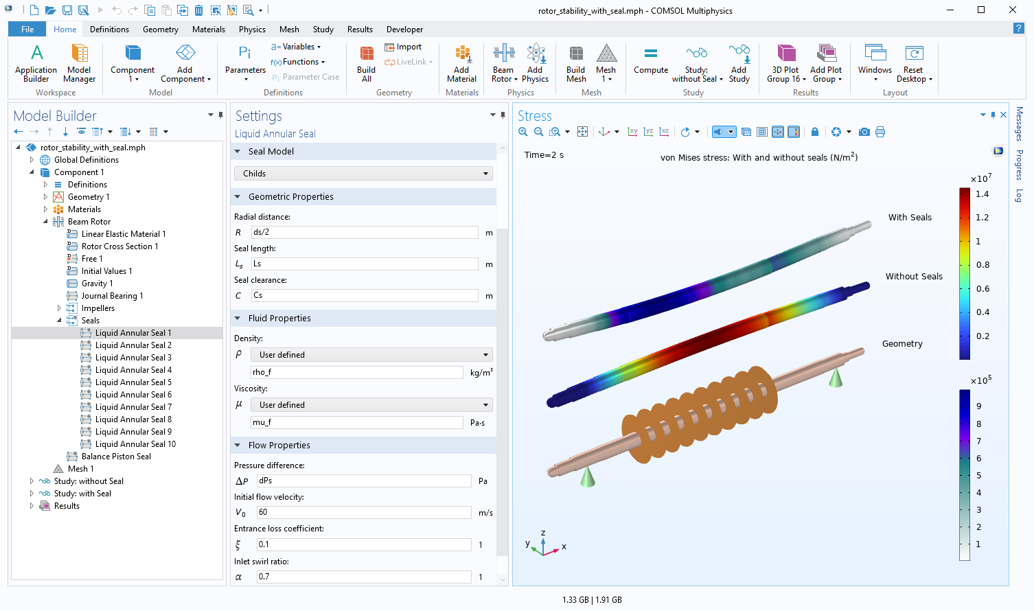
Liquid Annular Seal Modeling
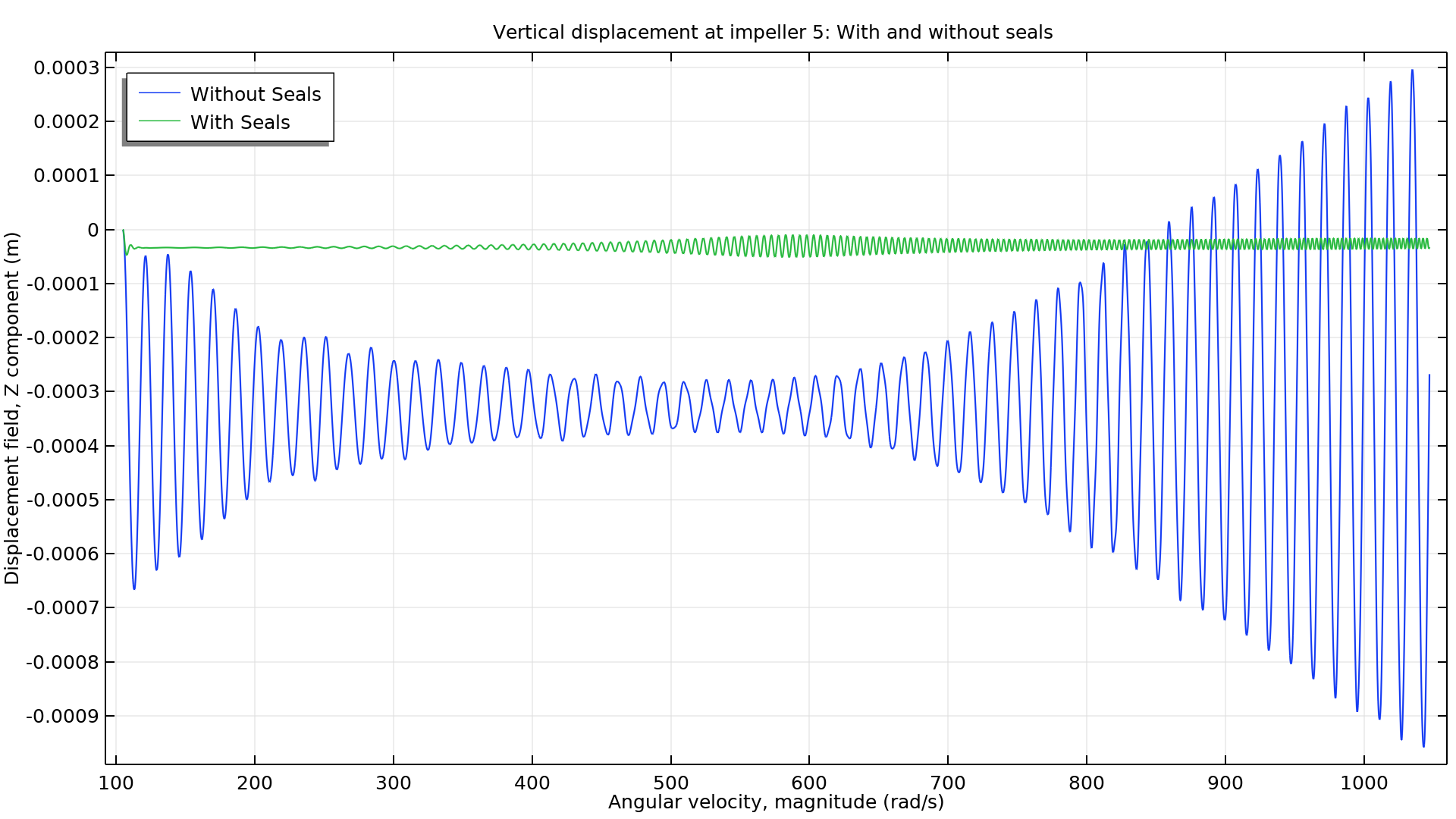
You can now model the effect of the flow in liquid annular seals on the dynamic response of the rotor using the Liquid Annular Seal feature available in all rotor interfaces. This feature provides two models, Black and Jenssen and Childs, to model the forces in seals in terms of dynamic coefficients. The Black and Jenssen model can be used for relatively longer seals but cannot account for the variation in the inlet swirling velocity of the flow in the seal. The Childs model is only valid for short seals but accounts for the variation in the inlet swirling velocity of the flow in the seal. You can see this new feature in the Response of a Rotor Under the Influence of Seal Forces tutorial model.
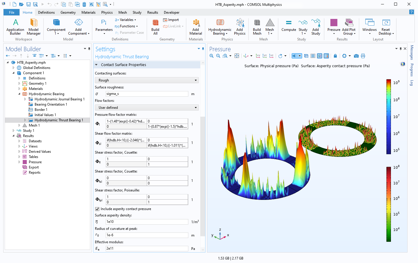
Turbulence Effect in Hydrodynamic Thrust Bearings
You can now model the effect of the turbulence and surface roughness in hydrodynamic thrust bearings using a set of flow factors and shear stress factors. This effect can be modeled in two cases:
- Turbulence induced due to high speed of the rotor with sufficiently smooth surfaces of the collar and bearings
- Turbulence induced due to roughness of the collar and bushing surfaces
In the second case, two lubrication regimes can be modeled: full-film lubrication and mixed lubrication. For full-film lubrication, the contact load is supported by the pressure in the lubricant film only. For mixed lubrication, the contact load is supported by both the lubricant film pressure and the asperity contact pressure. Mixed lubrication modeling is important in heavily loaded contact surfaces.
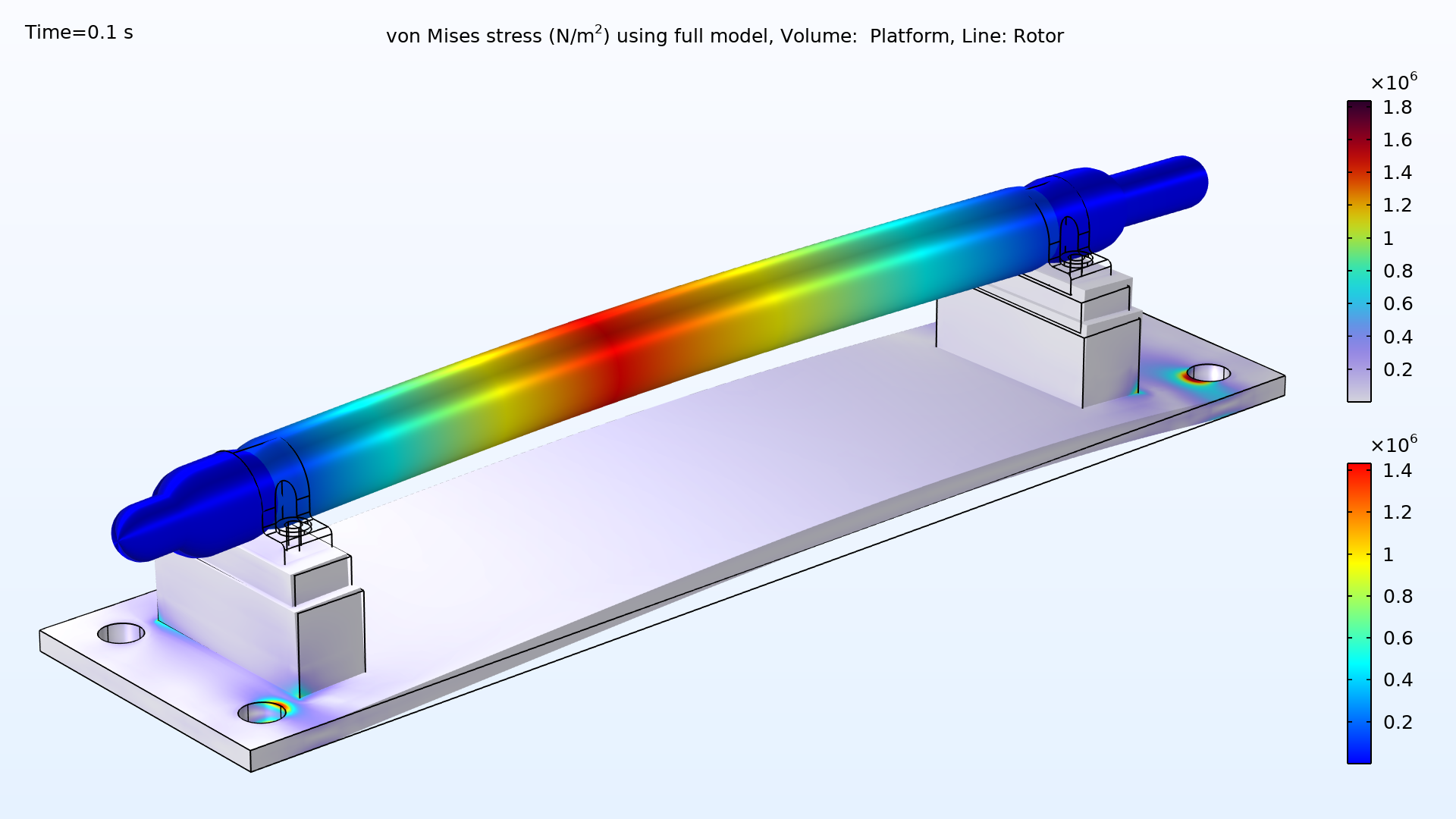
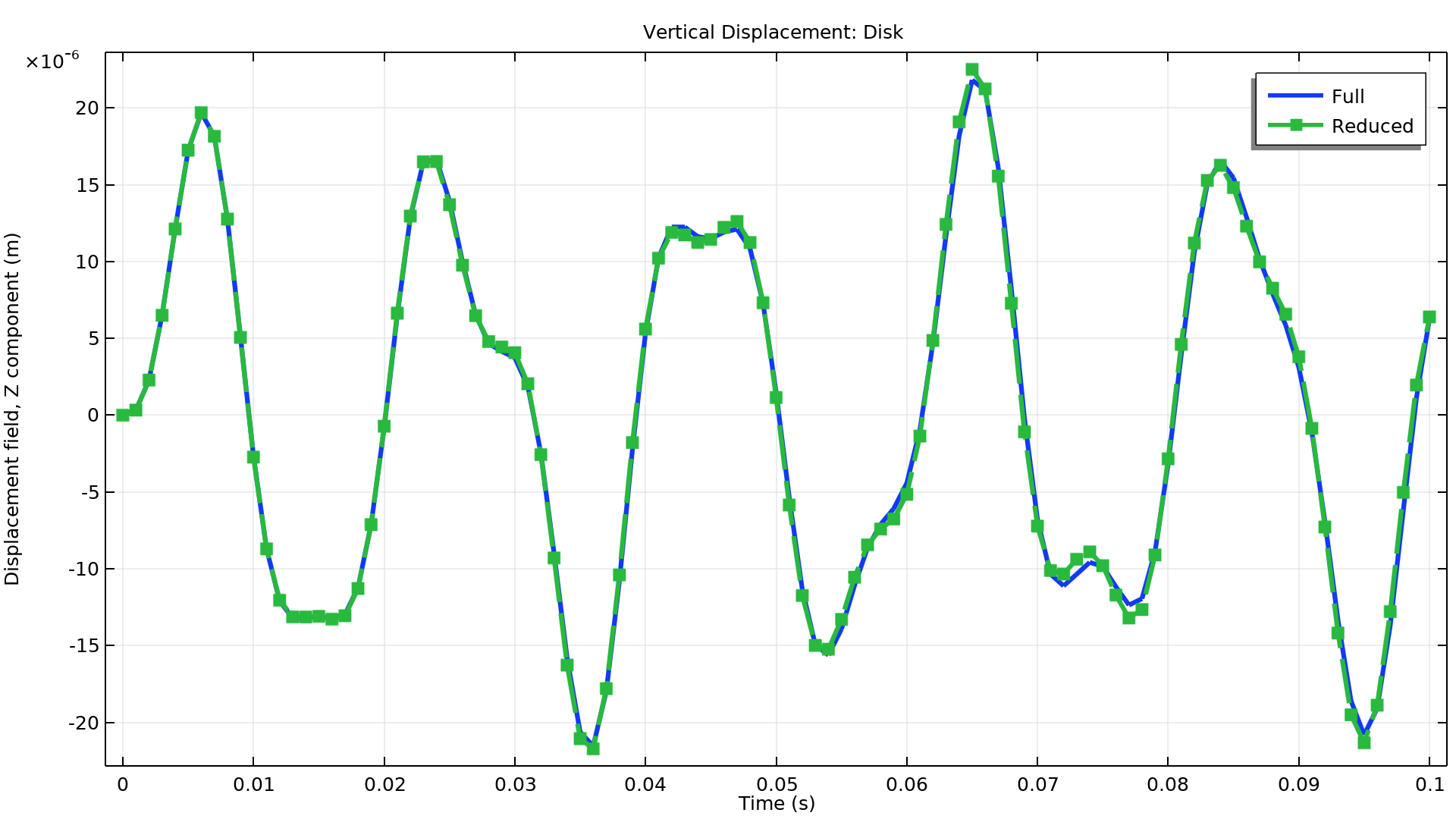
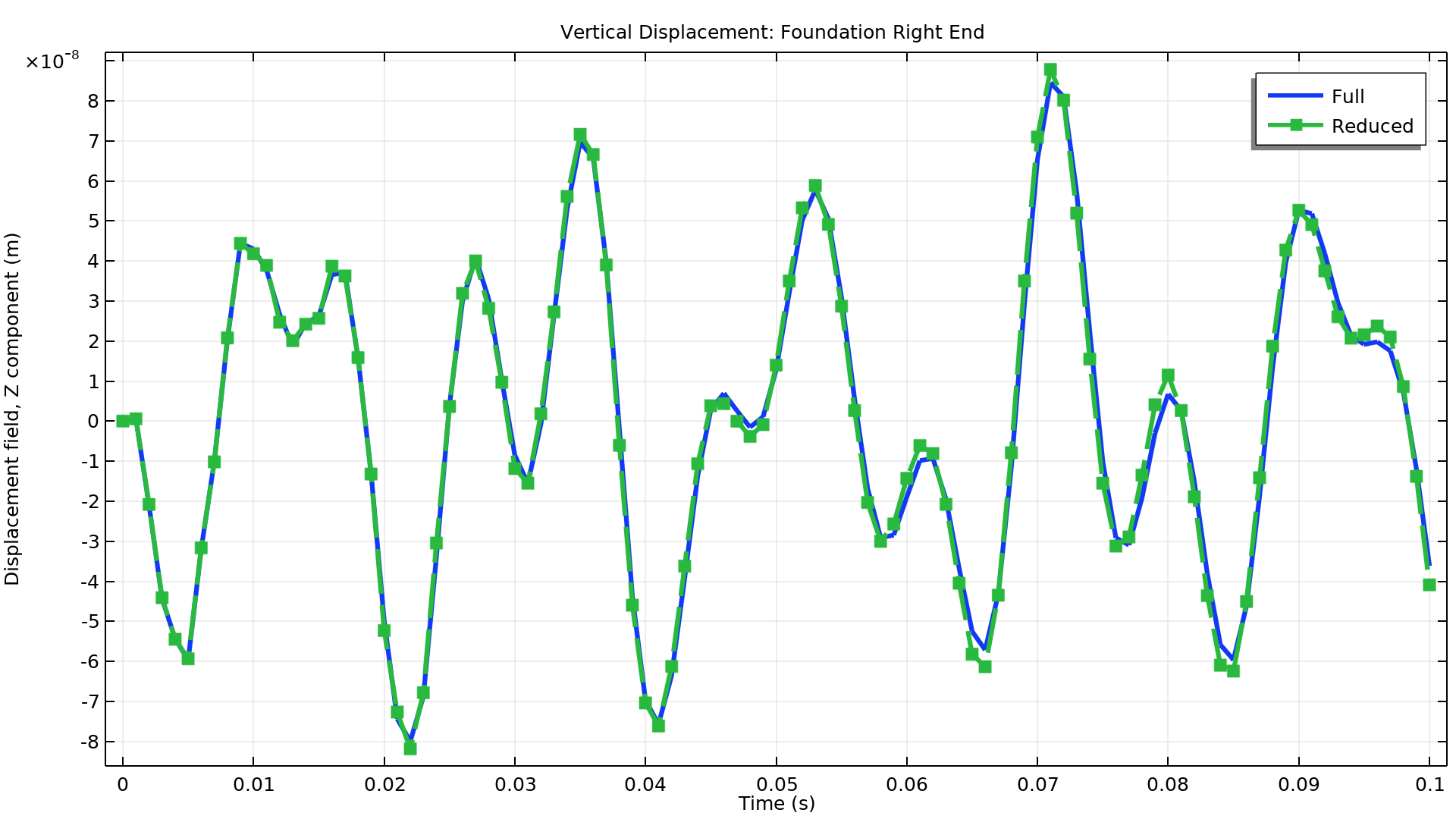
Component Mode Synthesis
You can now use the computationally efficient reduced-order models as a foundation for a rotor in a dynamic or stationary analysis. These reduced-order models are available for linear components that are built using the Solid Mechanics and Multibody Dynamics interfaces by performing a Component Mode Synthesis analysis using the Craig–Bampton method.

New Tutorial Models
COMSOL Multiphysics® version 6.0 brings two new tutorial models to the Rotordynamics Module.
Comparison of Campbell Plots Using Different Rotor Interfaces
Application Library Title:
campbell_plot_comparison
Download from the Application Gallery
Response of a Rotor Under the Influence of Seal Forces
Application Library Title:
rotor_stability_with_seal
Download from the Application Gallery