Using the Graphics Window
The Graphics window provides interactive visualization of the geometry, mesh, and results of your model in the COMSOL Multiphysics® software. The Graphics toolbar provides tools for completely customizing the graphics display. This functionality includes changing the view of your model; zooming in and out of the graphics display; and controlling other visualization options, such as lighting, transparency, or wireframe rendering. The functionality available depends on the spatial dimension of your model component as well as what node is currently selected in the Model Builder window.
Fundamental Graphics Window Operations
Watch the video below and follow along with your own model, or the busbar.mph exercise file, to learn how to use the functionality available through the Graphics window and toolbar during the model building process.
Using the View Node, Camera Node, and Shortcuts for Custom Visualizations of Your Models
There are many shortcuts you can use to control the camera and view angles to create great graphics of your simulation. The techniques shown here will help you produce graphics to visualize and present your work more easily.
Using the View Node
Even if you have spent plenty of time creating geometry, setting up models, and solving studies, there are many tools for arranging the graphics of your model that you may not have utilized yet.
The View node is one of the most important features in the graphics tools. This node is in the Model Builder window under Definitions. A single View node is automatically added when you create the first component in a model, but you can add more than one by right-clicking the Definitions node and choosing View. Having multiple View nodes lets you set up different perspectives of your model component’s geometry, which you can display in your results, and switch between them as needed. In the View node, you may also add and remove different types of lights and change their colors and positions.
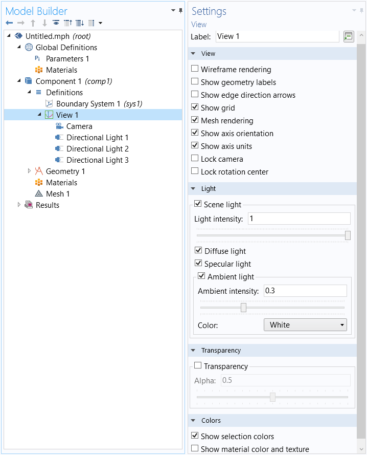
The View node in the model tree and the View Settings window.
In the View settings, you can control certain general effects (shown above), such as the overall light intensity, transparency, and whether a grid or coordinate system is shown.
Using the Camera
One of the many useful features of the View node is the camera. The Camera settings control the angle, position, zoom, and perspective of the camera, which correspondingly changes the view of the component geometry displayed in the Graphics window. Using the mouse and keyboard shortcuts that control the position of the camera is one of the most efficient ways to set up a good shot. One way to imagine the camera is to picture a physical camera sitting in front of the component geometry — the scene. When you look at the object, you are looking straight through the camera’s viewfinder at the scene, which is displayed in the Graphics window.
This means that when you move something in the Graphics window, you are actually moving the camera, not the geometry itself, unless you are performing a geometry operation. Here’s what the Camera settings look like:
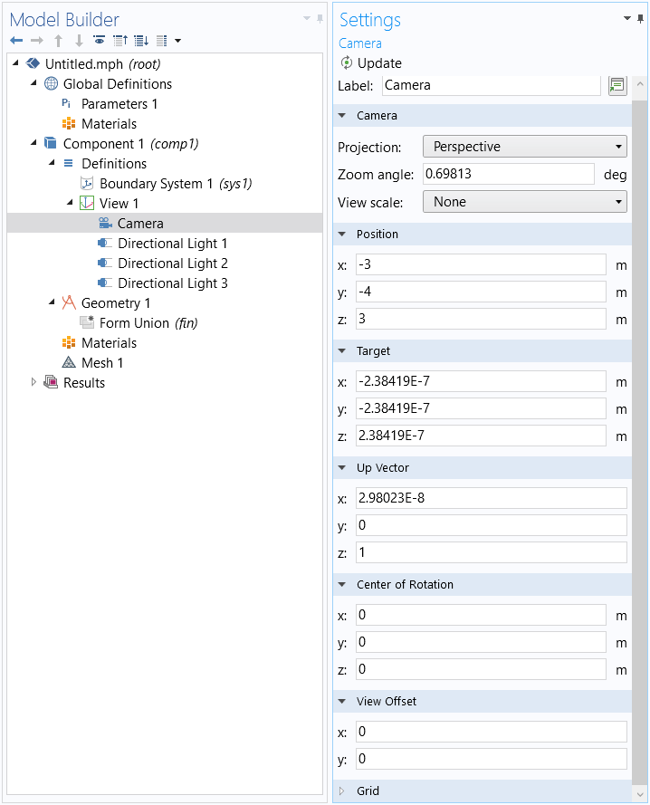
The Settings window for the Camera node.
Let’s run through a few of the settings shown above.
- Zoom angle
- This is exactly what it sounds like; the Zoom angle setting controls the zoom of the camera lens.
- Position
- This refers to the location of the camera, not the geometry object or scene. For instance, in the earlier image, the camera is located at coordinates (-3, -4, 3).
- Target
- This sets the target location, or where the camera is “looking”. For instance, a target of (0, 0, 0) means that the camera is aimed directly at the point (0, 0, 0).
- Another way to think about this setting is that it creates an axis through the center of the camera and the Target coordinates.
- Up Vector
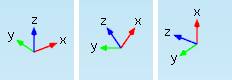
- This setting controls the direction of the camera’s up vector in relation to what is “up” in the model component or scene. An up vector of (1, 0, 0) tells you that you have tilted the camera 90 degrees and the camera’s up vector is running along the scene’s x-axis. The images below are examples of how changes to the camera’s up vector are reflected in the triad that shows the direction of the axis in the geometry, which is also the scene’s axis.
- Left, up vector set to (0, 0, 1); center, up vector set to (1, 0, 1); right, up vector set to (1, 0, 0).
- View Offset
- This setting moves the visible frame that the object sits in around on a plane that is parallel to the current Graphics window view (this does not refer to the xy-plane in the geometry’s coordinate system). The input values are relative to the size of the Graphics window — for instance, an x-value of 0.25 will move the scene in the camera’s viewfinder in the positive x direction by 25% of the width of the Graphics window.

Camera Shortcuts
Now, let's dive into positioning the camera to get the look you want. You can enter coordinates into the camera settings to obtain any view you need, but that option can be time consuming unless you know the exact coordinates for the position you want. Otherwise, you'll want to use the mouse and keyboard shortcuts to position the view.
Note: For macOS users, a couple of these shortcuts will only work on a two-button mouse or a mouse with a center button.
This first shortcut is simple, but very useful: it moves the visible frame left, right, up, or down on the camera’s viewfinder plane, the plane of the Graphics window. This changes the View Offset as described earlier.
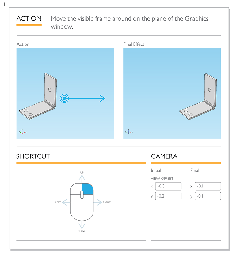
Infographic displaying how to move a model in the Graphics window.
The following shortcut rotates the camera around an axis perpendicular to the plane of the Graphics window:
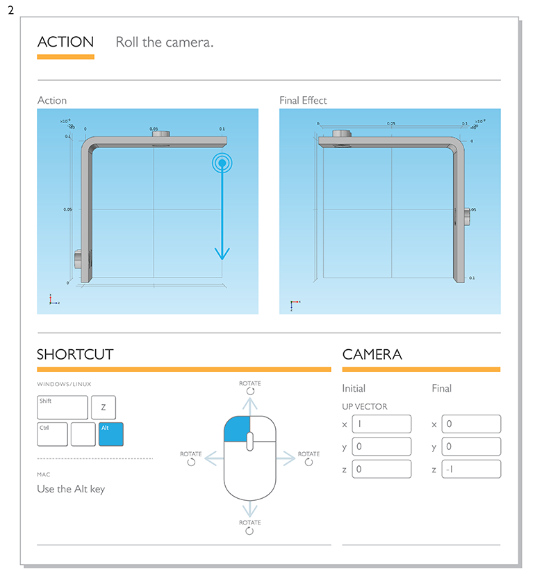
Infographic displaying how to rotate a model in the Graphics window.
Another simple but useful action is zooming in on the area where the mouse is located. While the zoom buttons in the graphics tools are quick and easy, they zoom in on the center of the visible window by specific increments. This mouse action gives you more precise control over the zoom angle.
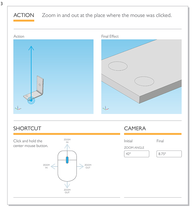
Infographic displaying how to zoom into or away from a model in the Graphics window.
The next shortcut changes the pan and tilt of the camera. This effect changes the position and angle at which the camera sees the component geometry (in contrast to the movement in Action 1, where the visible frame moves around in the camera’s viewfinder plane). The orange icon indicates the direction of the camera. Since this shortcut moves and rotates the camera with respect to the component geometry, the model will appear to move in the opposite direction of the mouse.
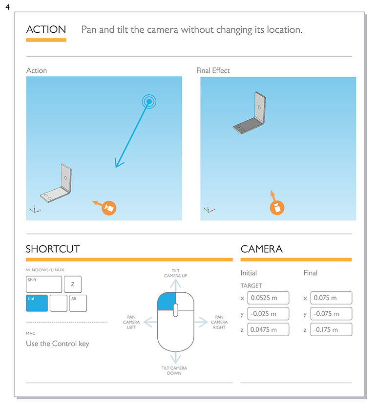
Infographic displaying how to pan and tilt the Graphics window.
Moving the camera up, down, left, and right (“pedestal” and “track,” if you’re in the movie business) is pretty easy once you know the trick. This shortcut moves the camera, but keeps it facing the same direction. Like Action 4, this gives a slightly different and more realistic perspective than simply moving the visible frame on the Graphics window plane. This shortcut also moves the camera with respect to the component’s geometry. Therefore, the geometry will appear to move in the opposite direction of the camera.
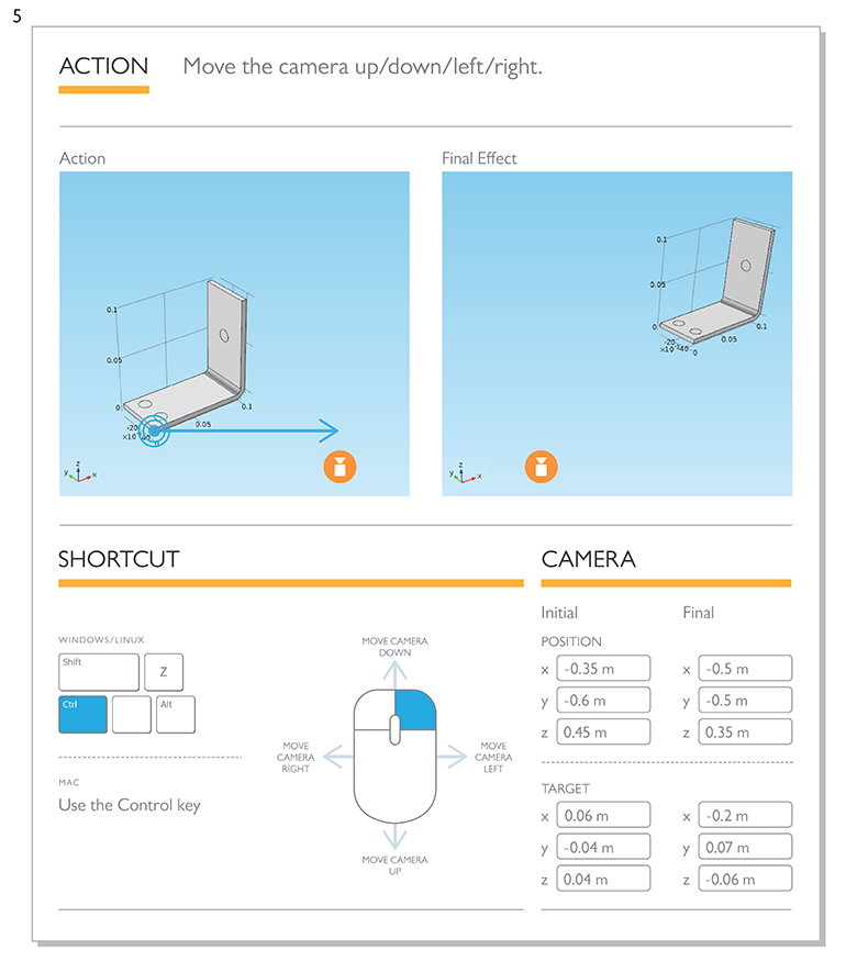
Infographic displaying how to move the camera up/down/left/right in the Graphics window.
This last shortcut keeps the component geometry in the center of the camera view, but dollies the camera in and out (forward and back) from the center of the view. Unlike zooming, it is not affected by the location of the mouse, nor does this action change the zoom angle of the lens. You can get really cool perspectives by first zooming out (Action 3) and then using the dolly shortcut to roll toward the scene.
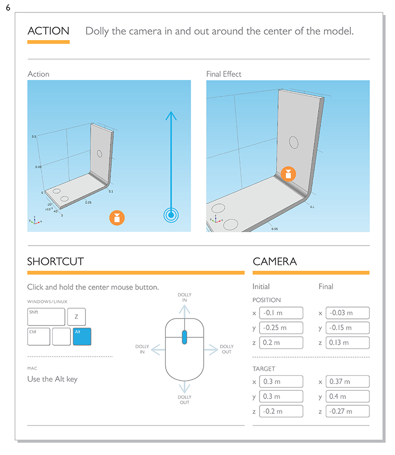
Infographic displaying how to dolly the camera in the Graphics window.
Microsoft and Windows are registered trademarks of Microsoft Corporation in the United States and/or other countries. Mac is a trademark of Apple Inc., registered in the U.S. and other countries. Linux is a registered trademark of Linus Torvalds.
Envoyer des commentaires sur cette page ou contacter le support ici.