

Signal Microwave develops high-frequency coaxial connectors in the RF and microwave industry, including end launch connectors, vertical launch connectors, and field replaceable connectors. At the COMSOL Conference 2018 Boston, Eric Gebhard of Signal Microwave discussed how using the COMSOL Multiphysics® software gives the company both a design and business advantage. Watch the keynote talk and get a quick summary below.
Eric Gebhard Discusses Design and Business Advantages of Simulation
Test Connectors Are a “Window” Between Devices and the World
Test connectors have a variety of uses, including:
- High-speed digital industry
- Military equipment
- Wireless systems
- Test equipment and labs
- Chip makers
More so, test connectors play an important role in how a device communicates with the world. As Eric Gebhard from Signal Microwave says: “Test connectors are the window between your device and the outside world.” If the “window” is hazy, the world is not going to see your device, and important details will be lost. A “clear window,” however, is a test connector with a transparent connection. It allows the world to see the device that you made.
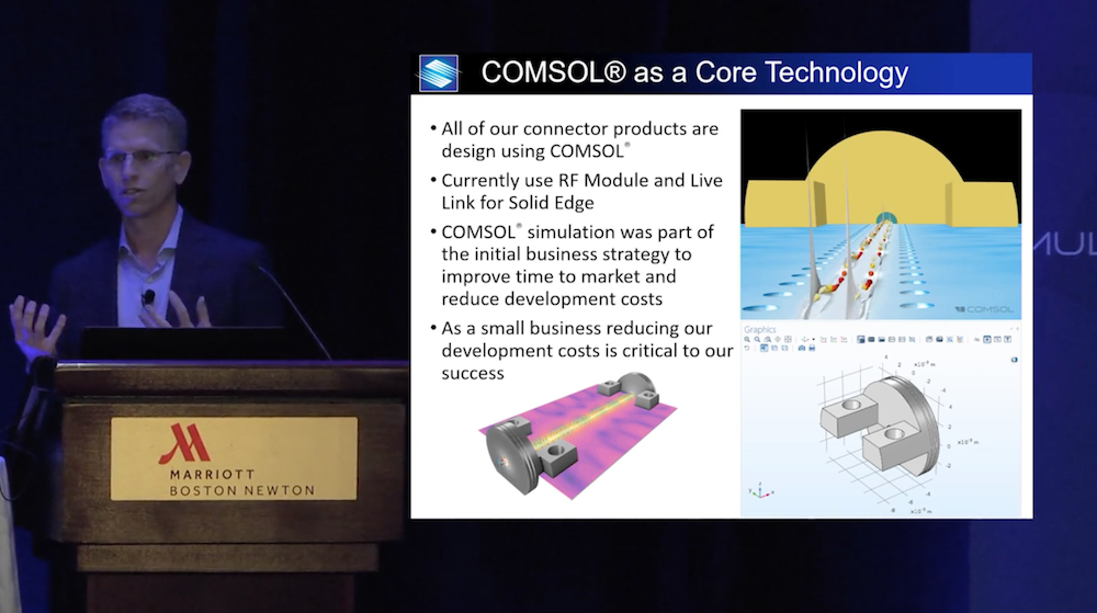
COMSOL Multiphysics® as a Business and Design Strategy
According to Gebhard, Signal Microwave uses COMSOL Multiphysics to design test connectors as part of their initial business strategy. Using simulation, the design teams are able to avoid testing failure within the development cycle, which helps them improve time to market and reduce development costs. These benefits are especially important to Signal Microwave “as a small business,” Gebhard says.
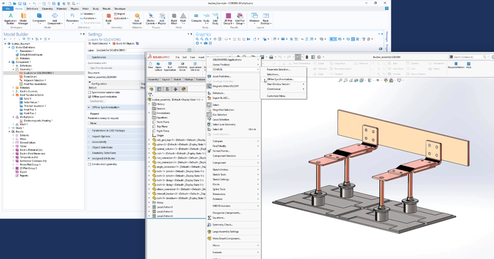
Gebhard also gives two examples of how Signal Microwave uses COMSOL Multiphysics®, as well as the add-on RF Module and LiveLink™ for Solid Edge® interfacing product, to design test connectors…
Push-On Connector
The first example is a push-on connector that Signal Microwave designed for Advantest with specific design requirements. The connector had to be mode-free to 70 GHz and have automated connection and disconnection, low reflections and losses, and compatibility with a float mount design. Perhaps most challenging was the time frame for the design: 8 weeks.
Eric Gebhard discusses how Signal Microwave uses simulation.
With simulation, Signal Microwave was able to create a prototype of the connector. However, when they got to the testing stage, the prototype didn’t meet the specific design requirements. Simulation again helped the team discover that the original prototype had a machining error, which they were then able to identify and fix before retesting a new prototype.
1-Millimeter Connector Design
The second example Gebhard demonstrates is a 1-mm connector design that Signal Microwave aimed to have ready in time for an International Microwave Symposium (IMS) show. The connector itself had specifications such as a bandwidth of DC to 100 GHz, a low voltage standing wave ratio, and a solderless connection. RF simulation was used to optimize the design of the board-layout interface, and the finished product was in fact ready in time to be presented at IMS.
RF simulation is a time- and cost-efficient way for Signal Microwave to bring optimized products to market, giving them both a design and business advantage.
Get more details from Eric Gebhard: Watch the keynote video at the top of this post.
Solid Edge is a trademark or registered trademarks of Siemens Product Lifecycle Management Software Inc. or its subsidiaries in the United States and in other countries.


Comments (0)