
Your finite element model will sometimes contain singularities — that is, points where some aspect of the solution tends toward an infinite value. In this blog post, we will explore the common causes of singularities, when and how to remove them, and how to interpret results when singularities are present in your model. While most of this discussion is in terms of structural mechanics, similar phenomena can also be found in many other physics fields.
The Problem
In my previous role as a structural analysis consultant, I sometimes came across the problem of how to report ridiculously high stress peaks in a finite element model to a customer. Experienced analysts know when stress peaks are an expected effect of modeling and can be safely ignored. Though, when a requirement that “the stress must nowhere exceed 70% of the yield stress” has been stated, this may still turn out to be an issue. Equally important is the fact that the small red spots in the color plots cannot always be ignored. Thus, we must have appropriate techniques for interpreting the model results.
The Sharp Corner: A Prototype of a Singularity
Sharp reentrant corners will cause a singularity in the derivatives of the dependent variables for all elliptic partial differential equations. In structural mechanics, this means that the strains can become unbounded since the degrees of freedom are the displacements. Unless limited by the material model, the stresses will also be infinite in such a case.
Stresses are investigated in the majority of structural mechanics analyses. This is why singularities present more of an issue in structural mechanics than in most other physics fields. In heat transfer analyses, for instance, you are much more likely to be interested in the temperature than in the local values of the heat flux, the area in which a singularity would become evident.
Let’s have a look at a prototype problem. This problem involves a 2 meters by 1 meter rectangular plate, featuring a square cutout with a side of 0.2 meters, that is subjected to pure tension:
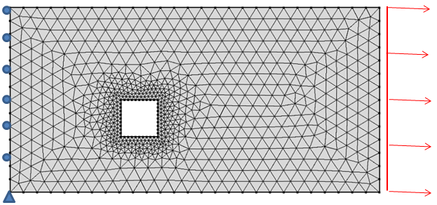
The plate is constrained along the left edge and has a uniform load along the right edge.
With two different meshes around the hole, the default plots of the equivalent stress look completely different. Since the peak stress is twice as high in the model with the finer mesh, most details in the stress field are lost. This can of course be remedied by manually adjusting the range of the plots, but it may hide important details at first glance.
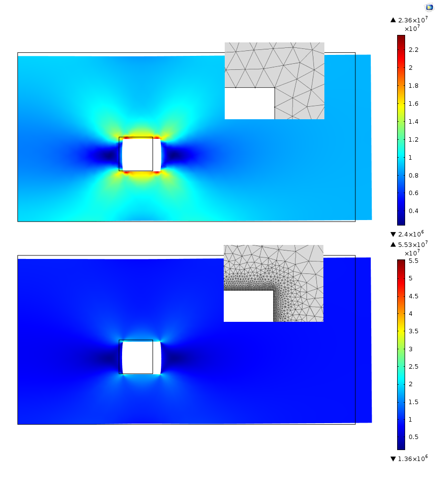
The same equivalent stress field in two plots. Both plots are automatically scaled by the mesh-dependent peak stress.
In fact, the smaller the elements that are used in the corner, the higher the values of stress that will be found. The results will not converge since the “true” solution tends toward an infinite value.
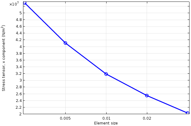
Stress at the corner as a function of element size (logarithmic horizontal axis).
If we investigate the stress field close to the hole, we will find that the stress peak is very localized. In the figure below, the stress is plotted along a vertical cut line drawn at a distance of 0.05 meters from the hole. At this distance, the stress is virtually unchanged, even though the peak stress at the corner varies by a factor of two.
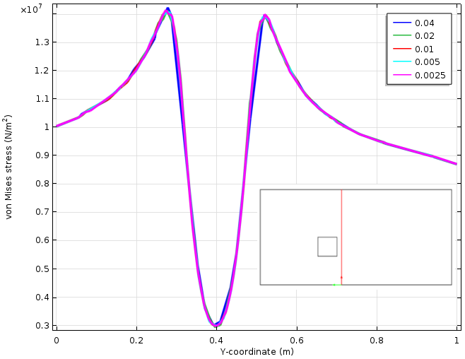
Stress variation along a cut line (represented in red). Five different mesh sizes are used.
In the real world, there are seldom perfectly sharp corners. Thus, you could argue that by using an accurate geometry representation containing all fillets, it is possible to avoid singularities. While true, this comes with a price tag. If very small geometrical details must be resolved by the mesh, the model grows enormously in size (especially the case in 3D). Even when a perfect CAD geometry is available, it is common practice to defeature the geometry to remove small details that are not important within the scope of the analysis. Therefore, in many cases, we actually deliberately introduce sharp corners at the preprocessing stage.
There are, however, some drawbacks to keeping the sharp corner:
- If the material model is nonlinear, there may be numerical problems at the singularity. For example, the strain rate predicted by a creep model is often proportional to a high power of stress. The high stress at the singularity (a value determined only by the mesh) raised to a power of five may result in strain rates so high that the time stepping is forced to be in the order of milliseconds, when you actually want to study an event taking place over months. If you still want to keep the sharp corner, the remedy here is to enclose the singularity in a small elastic domain.
- Adaptive meshing, error estimates, and the like can fail since the singularity will dominate over the rest of the solution. Exclude the corner from any such procedures.
- When running an optimization where stresses are part of the problem formulation, the singularity will lead to solutions that are optimal only in terms of reducing the amplitude of the unphysical peak stress. In the Multistudy Optimization of a Bracket tutorial, the region where the bracket is bolted is excluded from the search for a maximum stress.
- As previously noted, the high stress peaks tend to obscure more interesting features in the solution, both visually and psychologically.
Physically, if the corner is very sharp, the material will be damaged by the high strains. A brittle material may crack; a ductile material may yield. While it may sound alarming, such damage will only cause a local redistribution of the stresses in most cases. As seen from the perspective of the surrounding structure, the effect is no more dramatic than that of somewhat changing the fillet radius. High, very localized stresses will only be a true problem if the loading is cyclic, which creates a risk for fatigue.
In a building, nobody is concerned that the holes for windows and doors are rectangular with sharp corners. But, in an airliner, you will find that the windows are smoothly rounded since the variation between the pressure in the cabin and the pressure outside will provide a cyclic stress history.


Left: A rectangular window featuring sharp corners. Image by Jose Mario Pires. Licensed under CC BY-SA 4.0 via Wikimedia Commons. Right: A window with smoothly rounded corners. Image by Orin Zebest. Licensed under CC BY-SA 2.0 via Wikimedia Commons.
This is in fact recognized by many design standards, where high local stresses are allowed as long as the loads are static. The local corner stresses will not in any way affect the load-bearing capacity of the structure. Using this type of approach does rely on a systematic way of classifying the stress fields. Such methods are, for example, described in the ASME Boiler & Pressure Vessel Code.
For cyclic loads, on the other hand, it is important to obtain very accurate stress values. The fatigue life depends strongly on the stress amplitude. In this case, an accurate representation of the fillet is necessary, not only geometrically but also in terms of mesh resolution. If the model becomes too large to handle, you can use submodeling, an approach that is described in detail in this blog post.
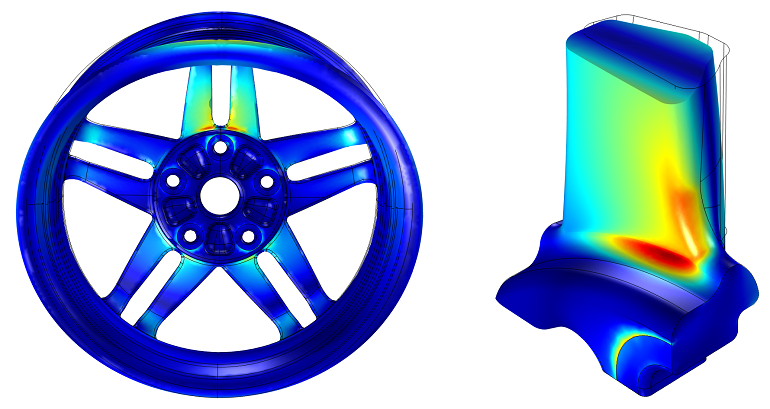
The detailed submodel on the right is driven by the results from the global analysis.
Tip: To further explore the submodeling technique, download the Submodeling Analysis of a Shaft tutorial from our Application Gallery.
Point Loads
A force applied to a single point on a solid will locally give infinite stresses. This is the classical Boussinesq-Cerruti problem in the theory of elasticity, where the stresses vary as the inverse of the distance from the loaded point.
In the real world, point loads do not exist. The force is always distributed over a certain area. From the finite element analysis perspective, the question is whether or not it is worth the effort to resolve this small region. The answer to that question lies in the Saint-Venant’s principle, which states that all statically equivalent load distributions give the same result at a distance that is large enough when compared to the size of the loaded area.
Thus, when detailed results are not important within a distance of, say, three times the size of the loaded area, it actually does not matter how you apply the loads, so long as the resulting force and moment are correct. Just as in the case with the corner singularity, you may still need to avoid the effects of singular stresses. Note that line loads will have the same effect as a point load in causing local infinite stresses.
It is interesting to make mention of the fact that a point load applied on a beam element or perpendicular to a shell will not induce a singularity. The bending of the structural elements is governed by equations other than solid mechanics. However, a point load applied in the plane of a shell will cause a singularity.
Constraints
If we think of a constraint in terms of its capability to apply a reaction force, it is evident that the same conclusions can be drawn as those for loads with respect to, for example, constraints applied to a point. But, that is not all. Consider the seemingly symmetric problem below. Here, we have a plate with a constant tensile load on one side and corresponding roller conditions on the other side.
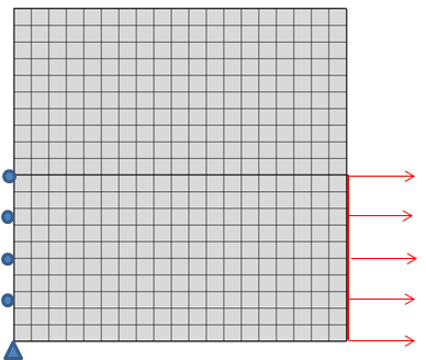
A square plate with one half of the vertical boundaries constrained and loaded.
When looking at the stress distribution, it is apparent that the end of the roller condition introduces a singularity that the sudden change in the load does not. A general observation is that the end of a constraint has an effect that is similar to that of a sharp corner.
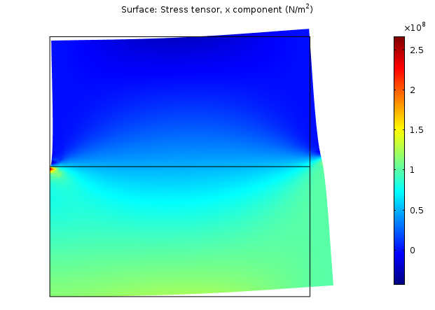
Horizontal stress distribution.
An infinitely stiff environment supporting the structure does not exist in reality. The analyst is again left with a choice: Can I live with the little red spot, or do I need to pay more attention to what is outside of my structure?
If the singularity caused by the boundary condition is not acceptable, you could consider the following approaches:
- Extend the model so that any singularity caused by the boundary condition is moved outside of the area of interest.
- Use a softer boundary condition by applying a Spring Foundation condition, for instance.
- Use infinite elements, which offer a cheap method for extending the computational domain. Learn more with this tutorial.
Situations similar to the one mentioned above are inevitable in many kinds of transitions. An example of such a transition is connecting a rigid domain to a flexible domain.
Welds
The art of analyzing welds is so important and complex that it warrants its own blog post. Here, we will only briefly touch on this subject.
Welded structures often consist of thin plates, so it is natural to use shell models in this context. Let’s have a look at the model below. In this example, a stress concentration is evident in the area where the smaller plate is welded to the wide plate.
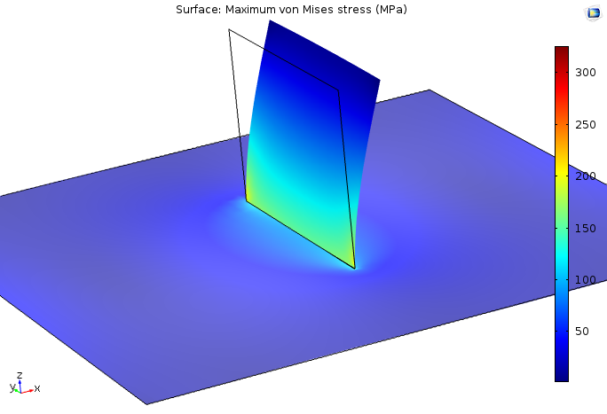
Stresses in a simple shell model of two plates welded together.
The geometry and loads are symmetric with respect to the center of the geometry. The mesh in this model, however, is designed so that it is much finer at one end of the weld. A graph of the stress along the weld line reveals a singularity in the stress field in both plates.
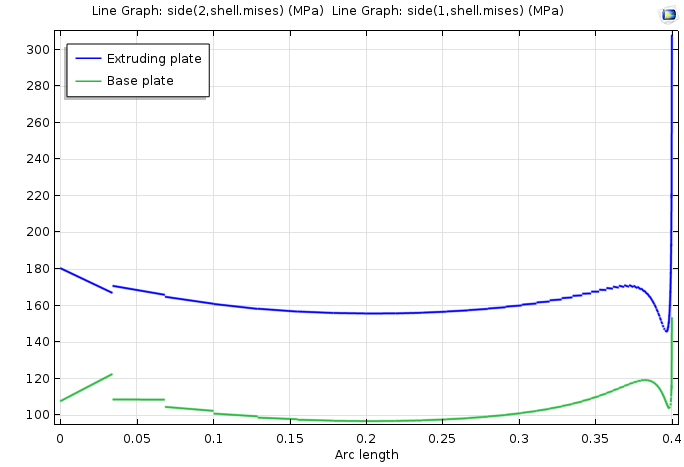
A stress plot identifying a singularity.
For many welded structures — ship hulls, cargo cranes, and truck frames — dimensioning against fatigue is important. Refining the modeling process by using a solid model is seldom the answer here. The local geometry and quality of a weld is rarely well defined, unless it has been ground and X-rayed. The local geometry will differ along the weld and between the corresponding welds on two items that nominally should be identical.
When analyzing welds, the most common approach is to average the stress along the weld line or along a parallel line a certain distance away. The cut lines in COMSOL Multiphysics are particularly helpful here. The local coordinate systems also come in handy since stress components parallel and normal to the weld need to be treated differently. These averaged stresses are then compared with handbook values, which are available for a number of weld configurations and weld qualities. To learn more, see Eurocode 3: Design of steel structures — Part 1-9: Fatigue.
Cracks
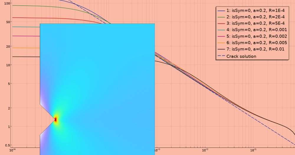
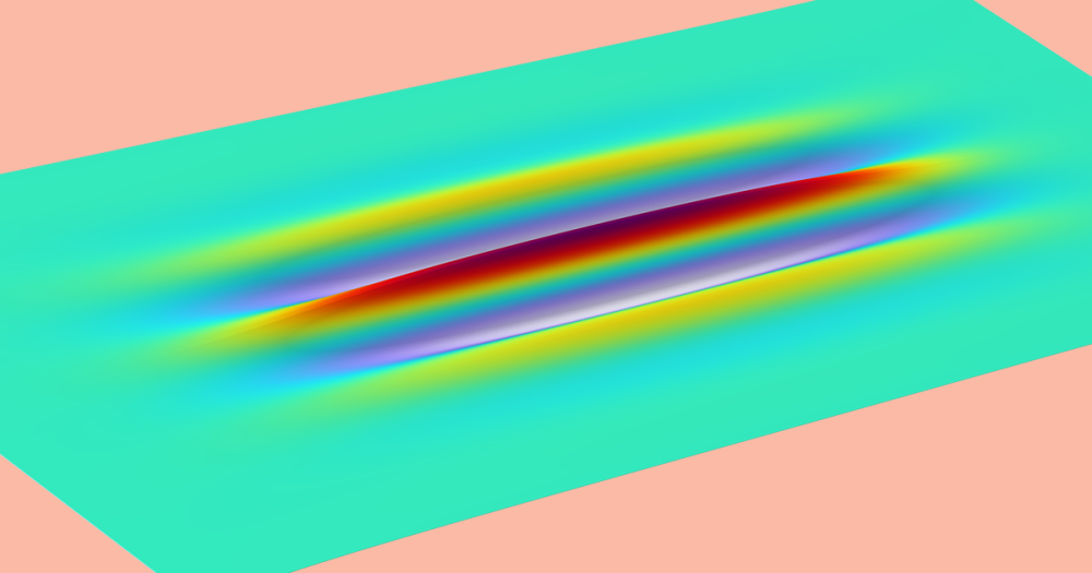
The worst conceivable geometrical singularity is the one caused by a crack. A crack can be seen as a 180° re-entrant corner, so many aspects of the corner singularity are also applicable here. When a crack is present in a finite element model, it is typically an area of focus within the study.
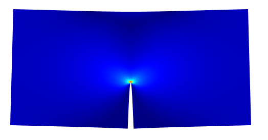
The stress field around a crack tip, with the deformation scaled.
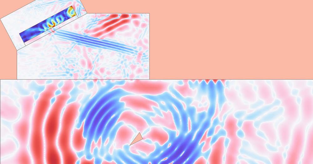
The stress field around the crack tip is known from analytical solutions, at least for linear elasticity and plasticity under some assumptions. Computing the stress field through finite element analysis, however, can be difficult due to the singularity. Fortunately, it is usually not necessary to study the details at the crack tip. When determining the stress intensity factor, for example, you can use either the J-integral or energy release rate approach. These methods make use of global quantities far from the crack tip, so that the details at the singularity become less important.
Tip: Looking to explore the use of the J-integral approach in further detail? Consult the Single Edge Crack tutorial in our Application Gallery.
Conclusion
Singularities appear in many finite element models for a number of different reasons. As long as you understand how to interpret the results and how to circumvent some of the consequences, the presence of singularities should not be an issue in your modeling. In fact, many industrial-size models require the intentional use of singularities. Keeping down model size and analysis time often necessitates simplification of geometrical details, loadings, and boundary conditions in a way that introduces singularities.

Comments (5)
Daler Amanbayev
April 6, 2018Thanks very much for such an explicit and concentrated post.
At the end you mention a Welds analysis. It is of a high interest, actually. Do you have plans to make such a post?
Henrik Sönnerlind
April 6, 2018Hi Daler,
Thank you for the kind comment.
I have no immediate plan to write a blog post about weld evaluation, but thanks for the reminder. It has earned its place on the long term to do list.
Regards,
Henrik
Henrik Sönnerlind
February 20, 2020 COMSOL EmployeeToday, one of my colleagues have published a blog post about weld stress evaluation:
https://www.comsol.com/blogs/how-to-predict-the-fatigue-life-of-welds/
Daniel Sundström
September 24, 2020To go back to the initial question “the stress must nowhere exceed 70% of the yield stress”, if we have a sharp corner and we are not interested by the local stress at the corner – is there any rule of thumb of how many elements from the corner where the stress levels should be evaluated?
Joao Gaspar
December 1, 2020Dear Henrik,
Thank you so much for such a clear and detailed explanation. It is definitely very useful for people who are starting FEA.
If possible, I would like to clarify two questions regarding the information given.
In the analysis performed to the sharp corner, it has been seen that at 50 mm from the hole (red line) the stresses are independent of the mesh size. My questions are then:
1) How do you estimate the stress level in regions closer to the hole where you still have a significant influence of the corner value?
2) Since the stresses near the corner cannot be used for analysis, how can we be sure that we won’t have problems in such areas?
Thank you for your time!
Best regards,
João