Terminology and Requirements for Swept Meshing
In the first part of this course, we learned the circumstances in which a swept mesh can be useful. In Part 2, we dig into the details of a Swept operation, including the associated terminology and when it can be used.
Terminology of a Swept Mesh
Let's start with some terminology used in COMSOL Multiphysics® for swept meshing. Within a domain to be meshed with the Swept operation, each face is classified as a source, destination, or linking face. The Swept operation begins at the source faces and ends at the destination faces, defining the sweep direction. Linking faces connect the source and the destination faces.
Linking edges are edges (or chains of edges) that are approximately tangent to the sweep direction, whereas section edges are edges (or chains of edges) that are approximately perpendicular to it.
A chain of section edges may form a loop around a domain, and in such cases the linking faces bounded by two such loops are referred to as a section.
Note that section faces may include additional isolated faces, such as the small rectangular-shaped face seen in the figure below.
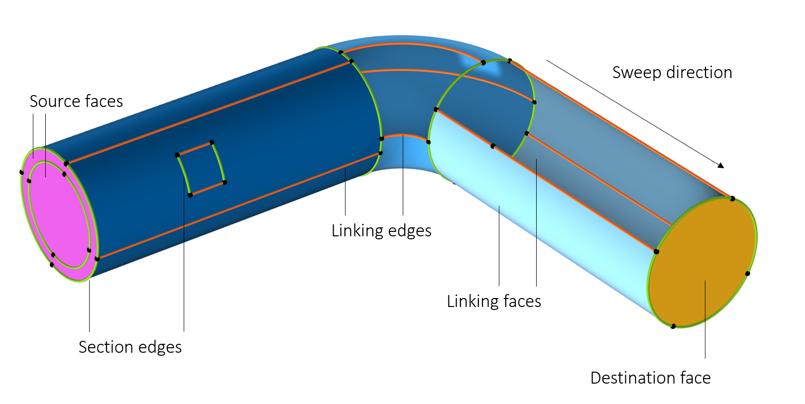
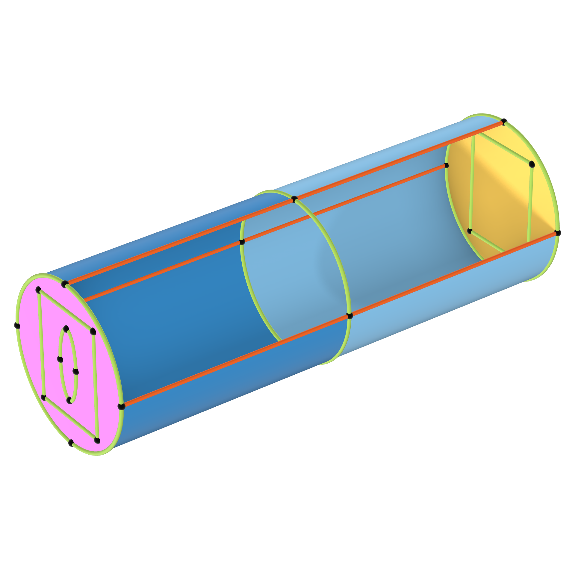
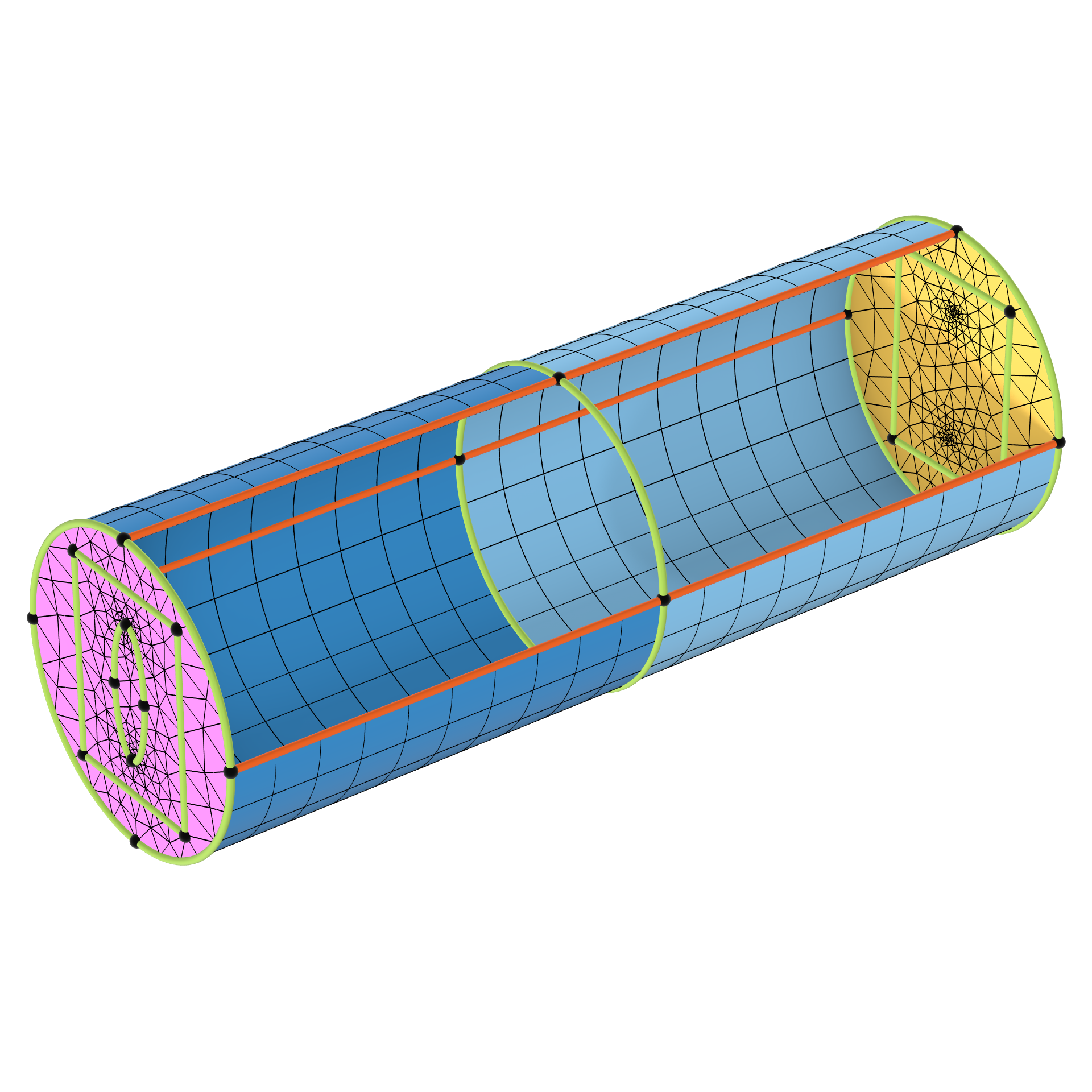
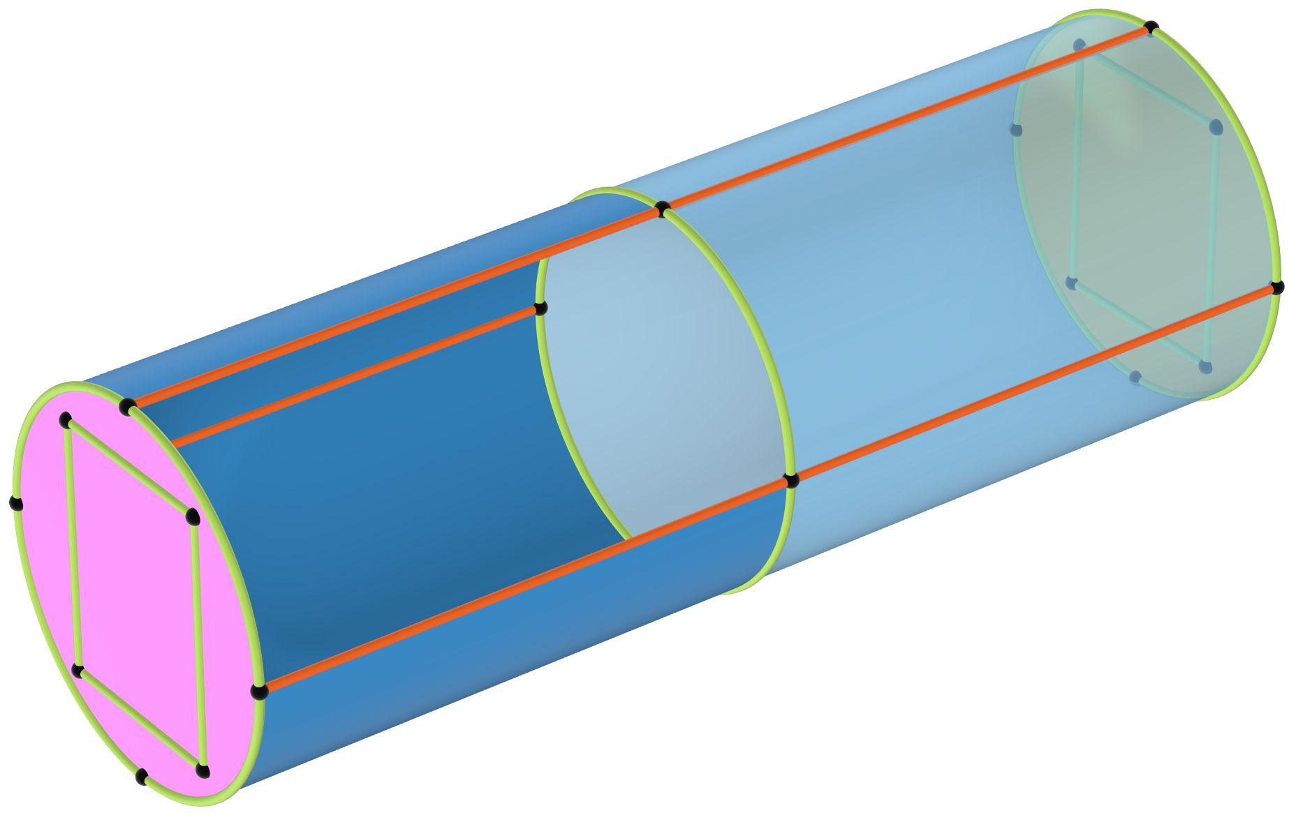
Classification of the boundaries and edges about a domain used for swept meshing. The sections are depicted by the three shades of blue. Two faces are hidden to show the inside of the domain.
Requirements for a Swept Mesh
The very first step before even trying to generate a swept mesh is to ensure that the domains are following several criteria, as described in the documentation, which can be loosely summarized with four major rules:
- There should not be any holes, isolated faces, or voids in the domain.
- For each domain, the destination must be a connected face component, and, as of version 6.4, the source faces can be disconnected face components.
- Each destination face should match one or more source faces, while each source face should match exactly one destination face or its subset.
- For each section, there must be at least two chains of linking edges.
We will explore each of these requirements in detail, as some technicalities were omitted deliberately in this list. Techniques to fulfill the criteria for a given domain can be found below and in the next part of this course.
Since each domain within the geometry selection that will be swept follows the same logic, we will focus on one domain in this part.
Requirements on the Shape of the Domain
Handling of Holes, Isolated Faces and Voids
A mesh can be swept through a domain if holes or isolated faces penetrate both source and destination, as shown in the next picture.
 Models with domains that include a hole and face that penetrate both the source and destination of the swept mesh.
Domains containing holes and isolated faces. The domains are sweepable because the hole and face penetrate both the source and destination. Note that the domain with the isolated face can be swept meshed because the interior boundary can be mapped meshed and follows the general direction of the sweep.
Models with domains that include a hole and face that penetrate both the source and destination of the swept mesh.
Domains containing holes and isolated faces. The domains are sweepable because the hole and face penetrate both the source and destination. Note that the domain with the isolated face can be swept meshed because the interior boundary can be mapped meshed and follows the general direction of the sweep.
 Models with domains that can be swept if they are first partitioned.
The domains to the left can be partitioned into smaller domains that are sweepable.
Models with domains that can be swept if they are first partitioned.
The domains to the left can be partitioned into smaller domains that are sweepable.
This domain has a hole that penetrates both the source and the destination, so a swept mesh can be generated. The hole is allowed to move and change size along the path, and the mesh is deformed accordingly. Note that the resulting morphed mesh can contain deformed elements that may not be suitable for simulations.
In addition, domains can contain void regions if they have a geometric thickness and a one-to-one mapping between the source and destination entities, as shown in the images below.
 A shell with a void inside.
 The void region show with a clip plane.
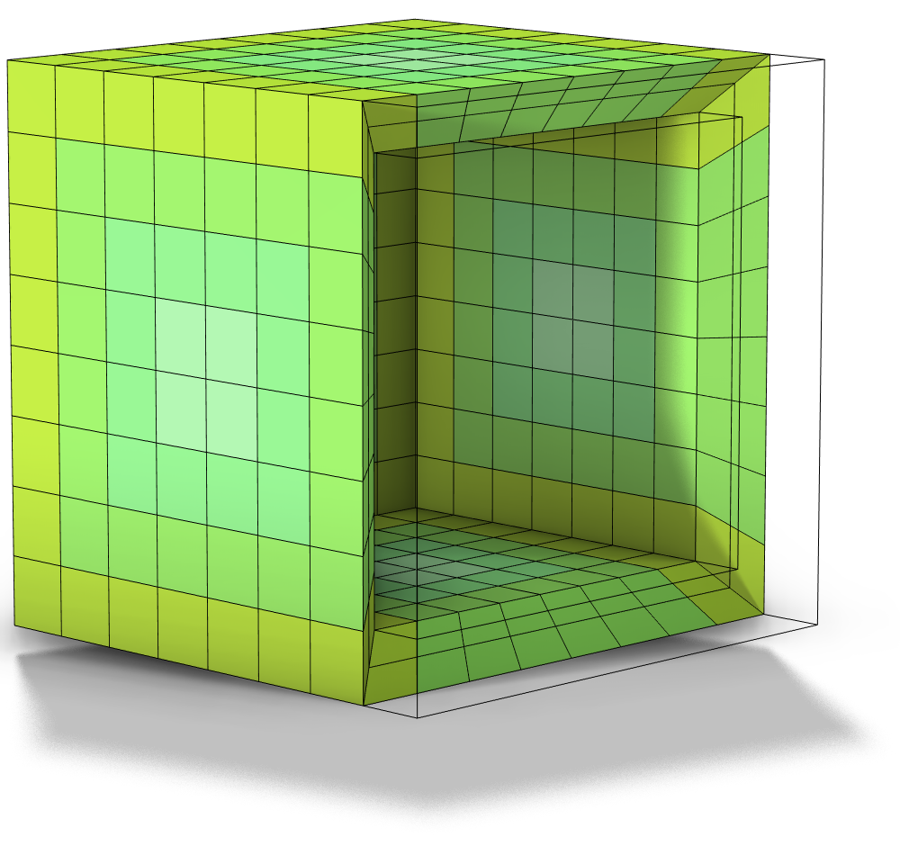 A plot of a swept mesh.
From left to right: 1) A shell domain with a void region inside it. 2) The void region, shown via a clip plane. 3) A plot of a swept mesh. Some elements have been filtered out for visibility.
How the Source and Destination Are Connected to the Domain
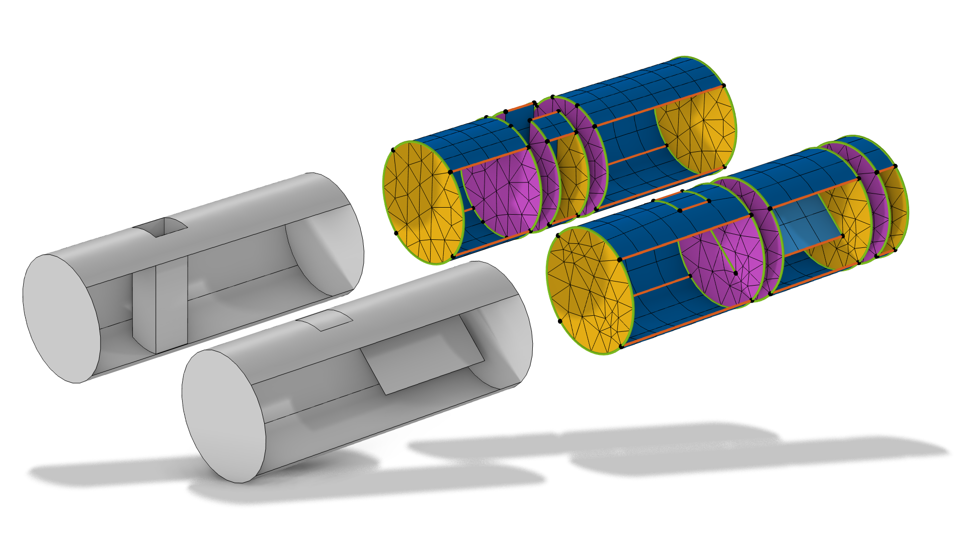
Let's now focus on the second rule. For each domain, the destination must be a connected face component, and, as of version 6.4, the source faces can be disconnected face components. Another way to interpret this rule on a domain level is to say that the domain can contain steps so that the source faces are located on different heights in the sweep direction. For a geometry that contains steps in both ends of the sweep, try to partition the domain into smaller pieces that can be sweepable (as shown in the image of the steel pipe below), or combine a swept mesh with a free tetrahedral mesh.
On a side note, coincident source and destination faces are allowed so long as the source mesh matches the destination (including any twists of the face), as shown in the animation of the torus below.
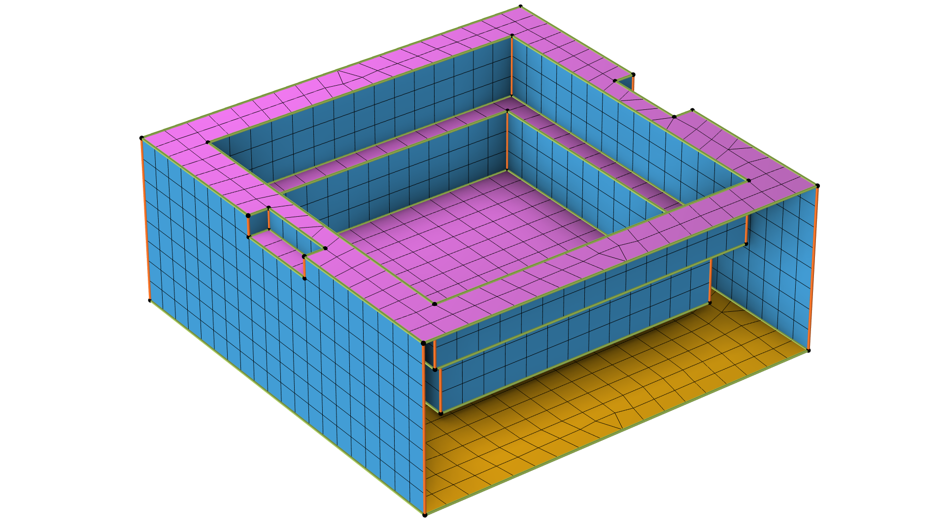 A rectangular 3D geometry with the faces shown with mesh elements.
This domain can be automatically swept meshed as of COMSOL Multiphysics® 6.4. The source faces (magenta) form a disconnected component as they are located on different heights while the bottom surface, the destination face, is a connected face component (yellow).
A rectangular 3D geometry with the faces shown with mesh elements.
This domain can be automatically swept meshed as of COMSOL Multiphysics® 6.4. The source faces (magenta) form a disconnected component as they are located on different heights while the bottom surface, the destination face, is a connected face component (yellow).
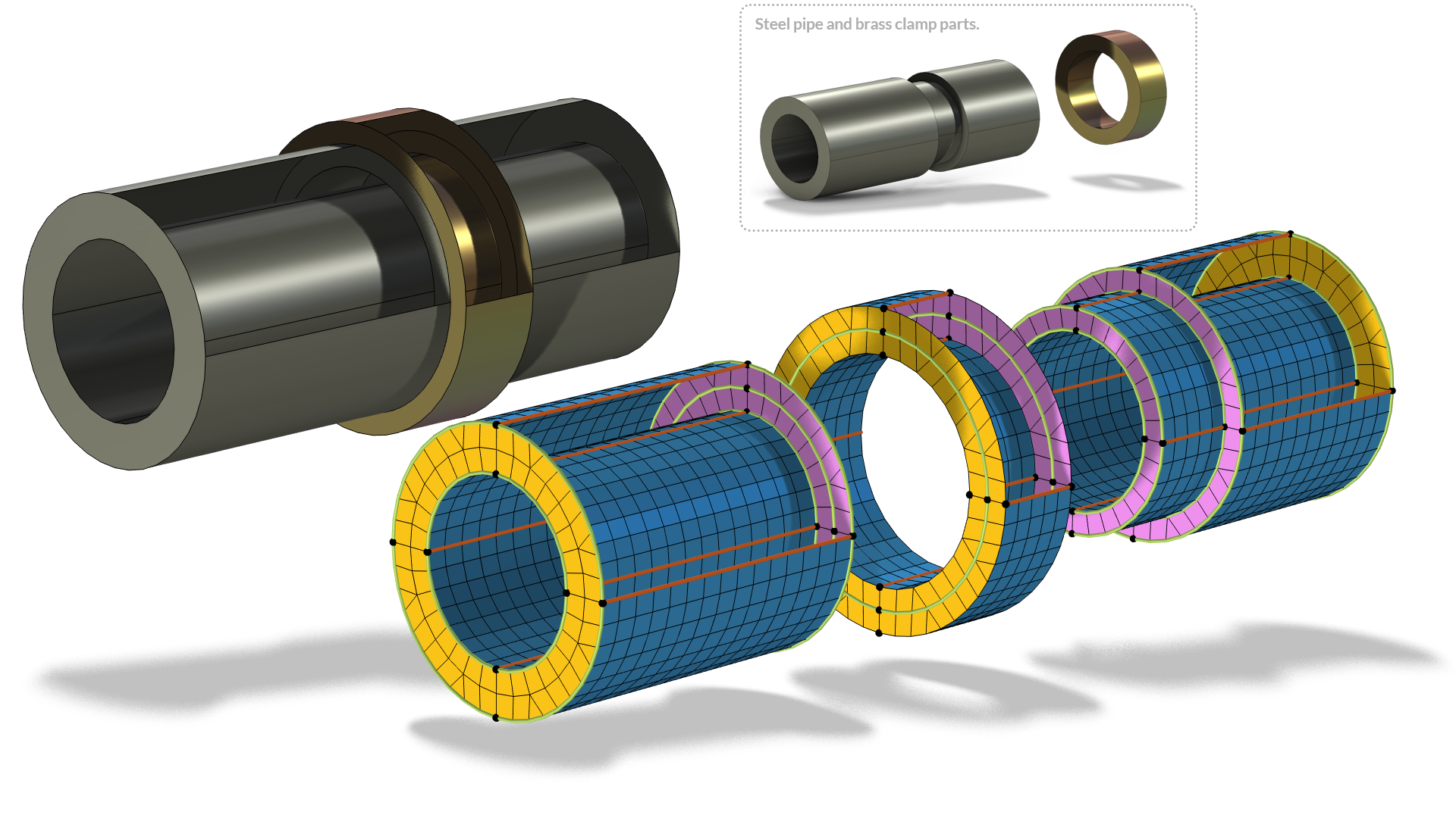 A cylindrical 3D geometry is shown assembled, in parts, with the faces colored in yellow, magenta, and blue and mesh elements applied.
The steel pipe to the left is one single domain with an indent where the brass clamp is located. By partitioning the steel domain with a work plane parallel to the side of the clamp, it is possible to sweep a mesh through the whole geometry (exploded view to the right).
A cylindrical 3D geometry is shown assembled, in parts, with the faces colored in yellow, magenta, and blue and mesh elements applied.
The steel pipe to the left is one single domain with an indent where the brass clamp is located. By partitioning the steel domain with a work plane parallel to the side of the clamp, it is possible to sweep a mesh through the whole geometry (exploded view to the right).
Following the square cross section of a meshed twisted torus, the surface mesh of the source needs to have 180-degree rotational symmetry due to the half turn.
Visualizing the Sweep Path
It is often helpful to mentally visualize the sweep by following the cross section of the mesh. An interpretation of the first two rules is that the cross section faces of a domain must match the destination faces similar to what is described in the Source and Destination Faces Requirements section. For example, a hole will create a void in the cross section, and a branching of the domain will create disconnected faces in the cross section. For the Y-shaped geometry below, the cross section split into two disconnected faces. See "How to Control the Swept Mesh" for an example of how to partition the geometry in order to sweep parts of it.
A visual interpretation on the reason why this Y-shaped domain needs to be partitioned before sweeping the mesh (left). On the right, a partial mesh is shown for visualization purposes in the portion where the domain could have been swept meshed if it was partitioned by the cross section, but in reality no mesh would be generated.
A way to help with this visualization is to add a Clip Plane that is parallel to the cross section of the sweep, and then drag the frame of the clip plane in the sweep direction. Make sure to select the option Show Cross Section.
This recording shows how to manually visualize the sweep path from the Graphics window. This domain encloses a void region, which is especially apparent because the cross section becomes hollow in the middle of the sweep path. The domain would need to be partitioned into three parts with a tetrahedral mesh in the middle domain, similar to the Y-shaped geometry above.
The Special Case of Isolated Entities
Isolated edges and isolated vertices are edges and vertices that are positioned inside a domain or face without being part of any loop of edges delimiting a face. When isolated edges and vertices are present, the mesh is first generated without considering isolated entities. Then, in the second step, the entities are included and essentially "glued" to the existing mesh by moving some nearby mesh nodes. The mesh conforms to the isolated entities during the sweep.
If the isolated entities are not needed, consider using Virtual Operations to remove them from the geometry. See this blog post for more information.
 The interior of a mesh with and without isolated entities on the linking faces.
Visualization of the interior mesh, without (left) or with (right) isolated entities located within the domain. The mesh on the right has been distorted in order to account for the additional entities during the sweep.
The interior of a mesh with and without isolated entities on the linking faces.
Visualization of the interior mesh, without (left) or with (right) isolated entities located within the domain. The mesh on the right has been distorted in order to account for the additional entities during the sweep.
Source and Destination Faces Requirements
Each destination face matches one or more source faces, while each source face matches exactly one destination face or its subset. In other words, the source faces can contain more faces than the destination, as long as there is a way of imprinting the mesh onto the destination (up to some distortion, like we saw in this animation).
 A geometry with more source faces than destination faces.
 A meshed geometry with more source faces than destination faces.
This geometry can be swept meshed even though there are more source faces (magenta) than destination faces (yellow).
For the majority of cases there is no deformation between the source and destination . One can simply translate and rotate the source faces to overlap on top of the destination faces. In such a case, it can help to mentally visualize copying the source mesh to the destination, and see if the copy operation is possible. This mental exercise is depicted in the next animations.
Only the source and destination faces are shown, following the same color convention as the previous 3D figure. Note that the source has more faces than the destination and that each destination face corresponds to one or more source faces.
An example where this rule is not adhered to: Since the destination has more faces, the mesh cannot be copied. The edges where the mesh copy failed are highlighted in red. Consequently, the direction of the sweep cannot be inverted for the previous 3D geometry.
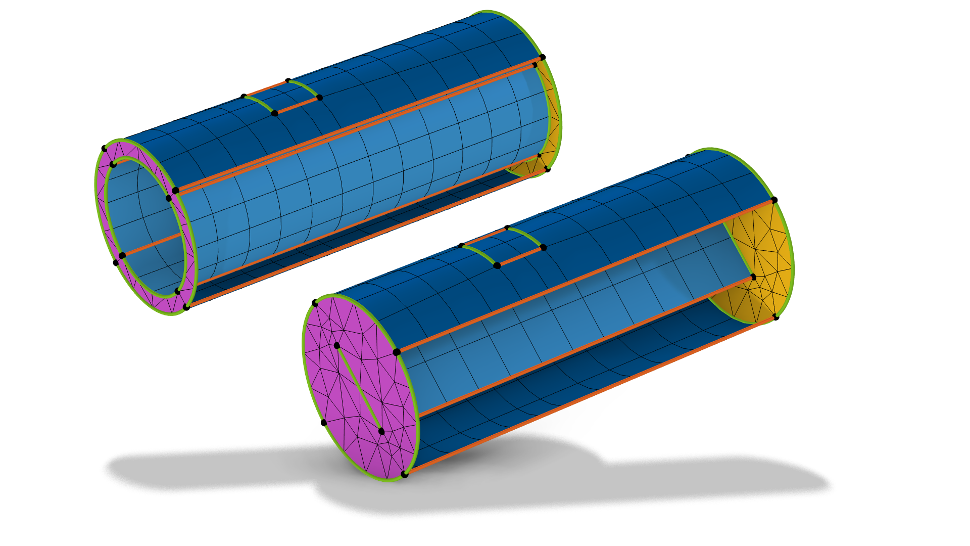
Imprinting some of the edges from the source to the destination, or vice versa, is one strategy to be able to sweep a mesh when there is a mismatch between the source and destination faces in domains or to make sure the sweep creates matching meshes along the sweep. The latter case is shown below.
 A cylindrical gray 3D geometry has two domains, which are also shown separately on the right, with the mesh elements and faces colored in magenta, blue, and yellow.
A geometry with two domains where it helps to imprint the rectangle edges on the middle face to make the geometry sweepable. Otherwise, there is no guarantee that the mesh swept from the top to the middle will be the same as for the mesh swept from the bottom to the middle.
A cylindrical gray 3D geometry has two domains, which are also shown separately on the right, with the mesh elements and faces colored in magenta, blue, and yellow.
A geometry with two domains where it helps to imprint the rectangle edges on the middle face to make the geometry sweepable. Otherwise, there is no guarantee that the mesh swept from the top to the middle will be the same as for the mesh swept from the bottom to the middle.
See more examples of imprinting here.
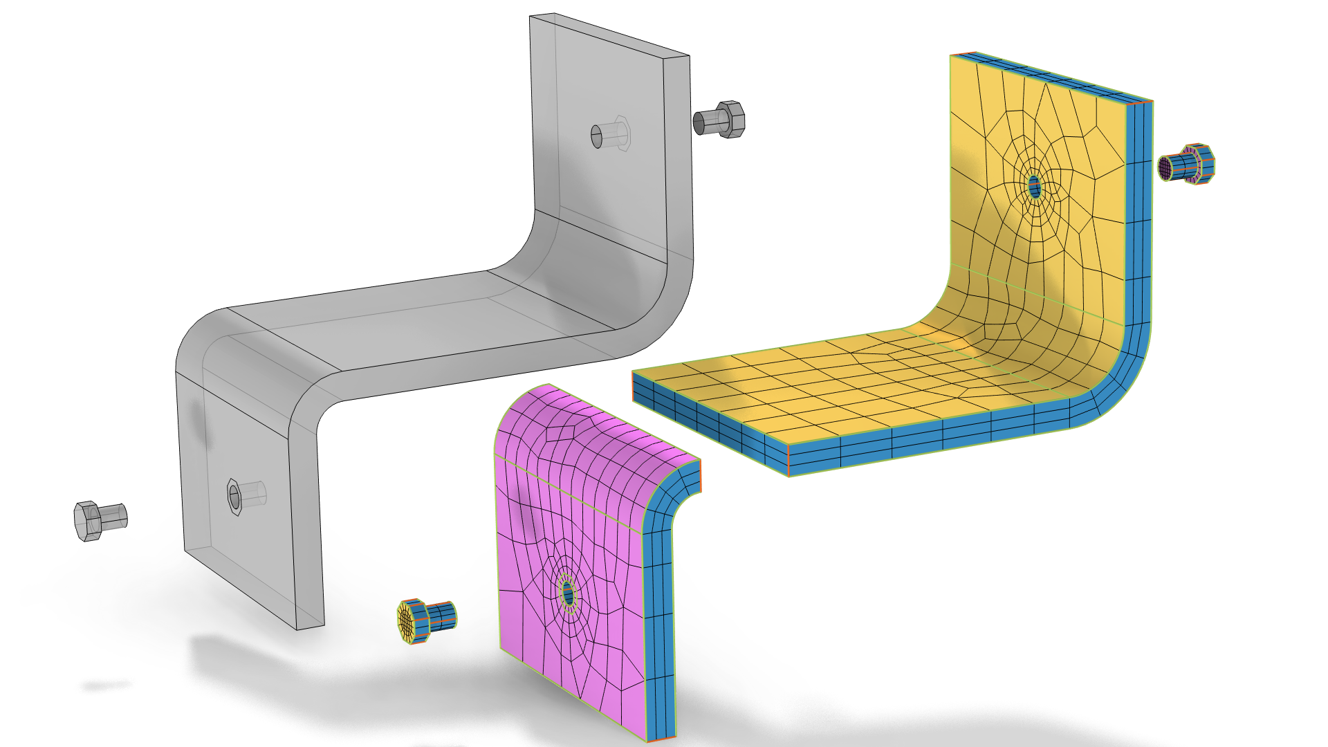 3D geometries of a gray, angled bracket and bolts are shown on the left, and the same geometry is shown on the right, with mesh elements applied and the faces colored in magenta, blue, and yellow.
To sweep a mesh through the angle bracket above (left), where there are imprints of the screws on opposite sides of the bracket, the domain can be partitioned in two (right) instead of imprinting the screw surfaces. Note that this geometry can be swept meshed with one Swept operation even though the two domains are swept in opposite directions.
3D geometries of a gray, angled bracket and bolts are shown on the left, and the same geometry is shown on the right, with mesh elements applied and the faces colored in magenta, blue, and yellow.
To sweep a mesh through the angle bracket above (left), where there are imprints of the screws on opposite sides of the bracket, the domain can be partitioned in two (right) instead of imprinting the screw surfaces. Note that this geometry can be swept meshed with one Swept operation even though the two domains are swept in opposite directions.
Linking Edges Requirements
For each section, there must be at least two chains of linking edges. Another way to interpret this rule is that there should at least be two linking faces per section.
 A domain with linking edges that can be swept meshed.
The domain can be swept meshed because there are at least two linking faces in both section (darker blue and lighter blue).
A domain with linking edges that can be swept meshed.
The domain can be swept meshed because there are at least two linking faces in both section (darker blue and lighter blue).
Concluding Remarks
In this article we discussed how to distinguish domains that can be meshed with a swept mesh and four simple rules to check for. To see how the swept mesh was generated for several of the model examples included in this article, you can see the respective MPH files attached. In the next part of the swept mesh course, we present the most important aspects to take into account so that you can generate a mesh that is suitable for simulations.
Envoyer des commentaires sur cette page ou contacter le support ici.