Please login with a confirmed email address before reporting spam
Posted:
1 decade ago
17 juil. 2013, 17:26 UTC−4
Hi,
Some thoughts...
Why can't you use continuation option so that the next step uses the previous step solution as its initial condition. But the only thing is that both your charge and concentration distributions are taken forward to the next step as initial conditions and not just concentration, I think. Is this what you want? If yes, you need to go to stationary, study extensions, select continuation and fill in the parameter range. When you select default solver, a parametric continuation solver will appear.
Out of curiosity, why can't you consider time dependent, in which case you have a time dependent voltage boundary condition?
Suresh
Please login with a confirmed email address before reporting spam
Posted:
1 decade ago
19 juil. 2013, 12:39 UTC−4
Hi Suresh,
Thank you for your response. Your input helped me for future trials - I didn't know of the continuation option within the stationary study step. However, my model requires a time-dependent study. I apologize for not being too explicit in my first inquiry about whether I was using a stationary or time-dependent study.
Could you please elaborate a bit more on your comment about the time-dependent study?
Thanks,
Buck
Please login with a confirmed email address before reporting spam
Posted:
1 decade ago
19 juil. 2013, 20:06 UTC−4
Hi,
To reflect your laboratory experiment wherein the voltage is varied in a particular fashion without restarting the experiment each time clearly means you are running a time depedent problem and not some sensitivity runs over a parameter range. So essentially you are running a coupled electrostatics (stationary) and ion transport problem (time dependent) in a time dependent mode for your electro-migration problem. You can therefore apply the voltage across the cell as a function of time via interpolation function (x-axis being time, y-axis the actual value of voltage). For this go to Functions, select interpolation and the default name will usually be int1. And under the boundary condition for voltage, type something like int1(t).
Please note I have not solved such problems in Comsol.
Suresh
Please login with a confirmed email address before reporting spam
Posted:
1 decade ago
9 juin 2015, 14:11 UTC−4
Hello,
I know this is quite an old thread. But I appreciate if anyone can help.
I've been trying for several days to do a similar simulation coupling the electric currents and transport of a dilute species modules. I'm not sure if I've set my physics correctly. In the original post Buck mentioned that he used a parametric sweep (-20V to 20V) to generate a potential gradient in the solution/bulk material. One of the questions I have is how would you set the "number of participating electrons" under "Electrode-Electrolyte Interface Coupling" when you do a parametric sweep(with positive and negative values) or applying a bi-phasic pulse to one electrode. Because the electrode changes from anode to cathode if I supply a bi-phasic pulse rather than a constant voltage.
Can anyone provide a sample model that answers this question. Thanks a bunch for any help or comment.
S.K.
Please login with a confirmed email address before reporting spam
Posted:
1 decade ago
10 juin 2015, 01:51 UTC−4
Hi
First, if you are working in aqueous solutions voltages like ±20 V does not make very much sense due to water splitting.
It all comes down with the electrode reaction: how is the transport coupled to that? If you tell your system, I can reply in more detail.
br
Lasse
Hi
First, if you are working in aqueous solutions voltages like ±20 V does not make very much sense due to water splitting.
It all comes down with the electrode reaction: how is the transport coupled to that? If you tell your system, I can reply in more detail.
br
Lasse
Please login with a confirmed email address before reporting spam
Posted:
1 decade ago
12 juin 2015, 09:22 UTC−4
Hi Lasse,
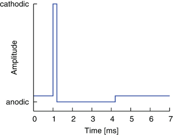
Thank you for your response. I'm actually trying to model a scenario of charge balancing. So assume two electrodes dipped in a saline solution. One electrode is grounded and the 2nd electrode is supplying a bi-phasic voltage pulse to the system (Ex pulse:
www.frontiersin.org/files/Articles/12119/fneng-04-00009-HTML/image_m/fneng-04-00009-g001.jpg). I would like to visualize the charges in the saline solution with time. The goal is to see some unbalanced charges around the electrodes if the positive area of the pulse is not equal to the negative area of the pulse. (
www.nervestudy.com/wp-content/uploads/2013/03/image013.jpg)
I've attached a sample model just with the EC physics.
Hi Lasse,
Thank you for your response. I'm actually trying to model a scenario of charge balancing. So assume two electrodes dipped in a saline solution. One electrode is grounded and the 2nd electrode is supplying a bi-phasic voltage pulse to the system (Ex pulse: http://www.frontiersin.org/files/Articles/12119/fneng-04-00009-HTML/image_m/fneng-04-00009-g001.jpg). I would like to visualize the charges in the saline solution with time. The goal is to see some unbalanced charges around the electrodes if the positive area of the pulse is not equal to the negative area of the pulse. (http://www.nervestudy.com/wp-content/uploads/2013/03/image013.jpg)
I've attached a sample model just with the EC physics.
Please login with a confirmed email address before reporting spam
Posted:
1 decade ago
12 juin 2015, 11:55 UTC−4
I have some troubles with the display with your model as I do not have CAD link: graphics window turns black.
But you have no coupling of transfer to electrostatics. Try Electrochemistry module, Primary Current Distribution. Also, the relative permittivity of a saline solution is somewhere around 70, not 1200 as you have defined.
br
Lasse
Please login with a confirmed email address before reporting spam
Posted:
1 decade ago
12 juin 2015, 16:14 UTC−4
I'm not sure I understand why your graphics window turns black. Here I've attached picture describing the model, it's nothing but three cubes. bottom surfaces of the electrodes touch the top surface of the cube that represent the saline. I know the dielectric values for saline are not correct. The values I used were some random values used for testing purposes.
Could you please help me set up the correct modules to do the simulation. I'm not sure I understand how to setup the primary current distribution. I was under the impression that 'electric current' module with 'diluted spices transfer module' would suffice to do the simulation.
Please login with a confirmed email address before reporting spam
Posted:
1 decade ago
13 juin 2015, 01:45 UTC−4
I wish you can open this; I am using version 5.0. I did no see the solution as my graphics window is black, but please tell me how it looked :)
In the Transport of Diluted Species, activate migration, inactivate convection. Choose Electric potential as "Electric potential (ec)".
Notice my changes in the time stepping and relative tolerance, as well as the diffusion coefficients and charge numbers, they correspond to NaCl. Concentration is 0.3 M, ca. the ocean salinity.
br
Lasse
Please login with a confirmed email address before reporting spam
Posted:
1 decade ago
13 juin 2015, 14:50 UTC−4
Hello Lasse,
The file did not open in version 4.4. Luckily I had access to a trial of version 5 and using that I was able to replicate the physics. Simulation works exactly as I expected and this solves most of the problems I had. Thank You so much for your help.
P.S. one of the resulting plots is attached.
Saliya K.
Please login with a confirmed email address before reporting spam
Posted:
1 decade ago
17 juin 2015, 12:34 UTC−4
Hello Lasse,
You were really helpful in understanding the use of transport of diluted spices module in my simulation. Could you please give me any suggestions on how to get the double layer capacitance effects into the same simulation. It seems like this effect is not simulated in the current system. Thank You.


