- Bridging the Terahertz Gap
- Modeling the Lithium-Ion Battery
- Protection contre la Corrosion
- Modélisation des batteries
- Modélisation et Simulation dans le développement des piles à combustible
- Modélisation thermique des petits satellites
- Analyse électro-vibroacoustique d'un transducteur à armature équilibrée
Electromagnetic Modeling of Induction Tool Responses in Layered Earth Formations
Introduction: This study presents the 3D electromagnetic model in layered media using induction logging tool. This algorithm utilizes electromagnetic wave frequency domain (EWFD) interface of Maxwell equations. Electromagnetic methods are popular tools for the measurement of resistivity (or conductivity) of the Earth formation. The purpose of our study is to show the effect of conductivity and depth for determining the electric field among single and multiple layered formations. In general, induction tool can operate deep inside the earth surface to measure the earth formation [1]. The induction logging tool was first invented by Doll in 1949 [2]. These tools can yield real-time formation parameters related with layer of earth as a function of depth. This method has an advantage of operating under complicated scenario without knowing the detail properties.
Use of COMSOL Multiphysics®: COMSOL Multiphysics® software is used to simulate the Electromagnetic (EM) field around the induction coil (i.e. transmitter and receiver). In order to obtain the electric field, we have used Radio Frequency (RF) Module with Electromagnetic Waves, Frequency Domain (emw) physics. Under EMW physics tree, scattering boundary condition is set as the outer boundary. Also, we have used AC/DC Module with Magnetic Field (mf) physics to solve for magnetic field. The materials used are air, steel AISI 4340 for the mandrel and user defined material for the different formation layer (i.e. different relative permittivity ∊r, relative permeability µr, electrical conductivity σ). A line source (I=1A) is assigned to the transmitter loop, called “Edge Current”. With 2 MHz frequency complex voltages at two receivers are calculated by using line integration. These voltages are obtained for different measured depth and electrical conductivity. Once the complex voltages are obtained, we used MATLAB® to calculate the attenuation and phase shift for that measured depth and electrical conductivity. Figure 2 reports the 3D geometry.
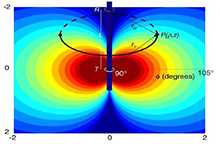
Results and Conclusion: The 3D models are developed for the representation of EM field using induction logging tool. Figure 3 reports the electric field distribution at σ = 0/0056 S/m.These tool are applied in normal direction (i.e. z-direction) and horizontal direction (i.e. x-direction) of the beds to obtain electric field and complex voltages.
Téléchargement
- shakya_poster.pdf - 1.19MB
- shakya_abstract.pdf - 0.1MB