
Basic Emission and Immunity Analysis of a Circuit Board
Application ID: 89061
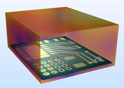
This model example shows how to simulate basic electromagnetic interference (EMI) and electromagnetic compatibility (EMC) behavior in a printed circuit board (PCB). The model contains two analyses to evaluate radiated emissions from PCB traces, crosstalk between adjacent microstrip lines, and the effect of an incomplete shield in a plastic enclosure.
For the first study, one microstrip line is excited to compute the crosstalk to a neighboring printed line and the radiated field that passes through the enclosure shielding. The second study investigates radiated immunity by analyzing how the circuit board responds to electromagnetic radiation from an antenna located outside the enclosure.
This model example illustrates applications of this type that would nominally be built using the following products:
however, additional products may be required to completely define and model it. Furthermore, this example may also be defined and modeled using components from the following product combinations:
The combination of COMSOL® products required to model your application depends on several factors and may include boundary conditions, material properties, physics interfaces, and part libraries. Particular functionality may be common to several products. To determine the right combination of products for your modeling needs, review the Grille des spécifications and make use of a free evaluation license. The COMSOL Sales and Support teams are available for answering any questions you may have regarding this.


