Thermal-Stress Analysis of a Turbine Stator Blade
Application ID: 10476
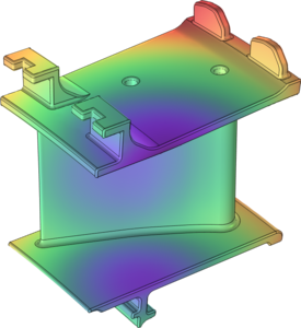
This example shows how to compute thermally induced stresses in a turbine stator blade using the Thermal Stress, Solid interface.
The conditions within gas turbines are extreme. The pressure can be as high as 40 bar, and the temperature more than 1000 K. Any new component must therefore be carefully designed to be able to withstand thermal stresses, vibrations and loads asserted by the fluid rushing through the turbine. If a component fails, the high rotational speeds can result in a complete rupture of the whole turbine. The most extreme conditions are found in the high pressure part downstream of the combustion chamber where hot combustion gases flows through a cascade of rotors and stators. To prevent the parts from melting, air is led from the compressor past the combustion chamber, and is used as a coolant. Directly behind the combustion chamber, both internal cooling and film cooling is applied. Further downstream, where the temperature is somewhat lower, it may suffice with internal cooling. Since the physics within a gas turbine is very complex, simplified approaches are often used at initial stages of the development of the new components. In this model, the thermal stresses in a stator blade with internal cooling are analyzed.
This model example illustrates applications of this type that would nominally be built using the following products:
however, additional products may be required to completely define and model it. Furthermore, this example may also be defined and modeled using components from the following product combinations:
- COMSOL Multiphysics® et
- soit le Module CFD, ou Module Heat Transfer et
- soit le Module MEMS, ou Module Structural Mechanics
The combination of COMSOL® products required to model your application depends on several factors and may include boundary conditions, material properties, physics interfaces, and part libraries. Particular functionality may be common to several products. To determine the right combination of products for your modeling needs, review the Grille des Spécifications and make use of a free evaluation license. The COMSOL Sales and Support teams are available for answering any questions you may have regarding this.