Meshing Updates
COMSOL Multiphysics® version 5.3 brings many improvements to your meshing operations and capabilities. Most importantly, the transition from hexahedral/prismatic mesh types to tetrahedrals is now automated by including pyramid elements. Furthermore, new tools to measure mesh quality and extend mesh manipulation through expressions have been included for you. See all of the mesh updates below.
Automatic Transitions When Meshing from Hexahedrons/Prisms to Tetrahedrons
Sometimes, you may want to use different mesh types to describe different parts of your geometry, but you have to join them at the interfaces in some fashion. Before COMSOL® software version 5.3, you would use the Convert operation to connect swept meshes to unstructured tetrahedral meshes. Now, the Free Tetrahedral mesh operation will automatically insert a layer of pyramid elements between the swept hexahedral/prismatic elements and the tetrahedral elements. The pyramid elements will appear in the domain where the Free Tetrahedral operation has been applied.
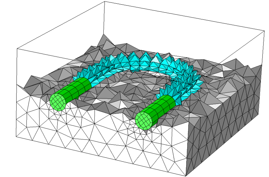
The Free Tetrahedral operation now automatically generates a layer of pyramids (cyan) around the hexahedrons (green) of a swept mesh, while filling the remaining space with tetrahedrons (gray). The pyramid elements are introduced within the tetrahedral part of the modeling domain.
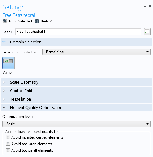
Optimized Tetrahedral Meshing to Avoid Small Elements
A new optimization option in the Free Tetrahedral operation has been introduced in order to avoid the creation of elements that are too small. You can use the Avoid too small elements option if you would like to maximize the size, measured as the radius of the inscribed sphere, of the smallest elements while still respecting the desired local element size. This optimization improves performance when solving problems using explicit time-stepping.
Mesh Size Expressions
A new mesh attribute introduces more flexibility for manipulating mesh size and distribution. The Size Expression node can be added to a meshing sequence in the Model Builder in order to vary element size throughout the modeling space using expressions. You can select whether the expression should be evaluated on a grid or on a solution. If you use the Grid option, an expression can be included in the Size expression edit field based on global variables defined by parameters, functions, materials, and variables. If you use the Solution option, the expression can be entered using variables defined by the solution, such as the error estimation variables.
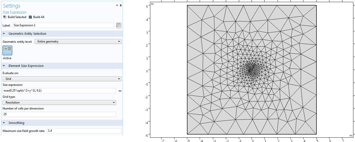
An expression based on geometric parameters in the modeling domain, thus evaluated on the grid, has been added to the Element Size Expression section in the Size Expressions Settings window (left). This results in the size and distribution of elements seen in the modeling domain (right).
Mesh Adaptation Based on Error Expressions
A new operation called Adapt refines your mesh based on either an expression for the error in a solution or by an expression for the desired mesh element size. The adaptive solver then uses this operation to create adapted meshes.
New Tools for Evaluating the Quality of a Mesh
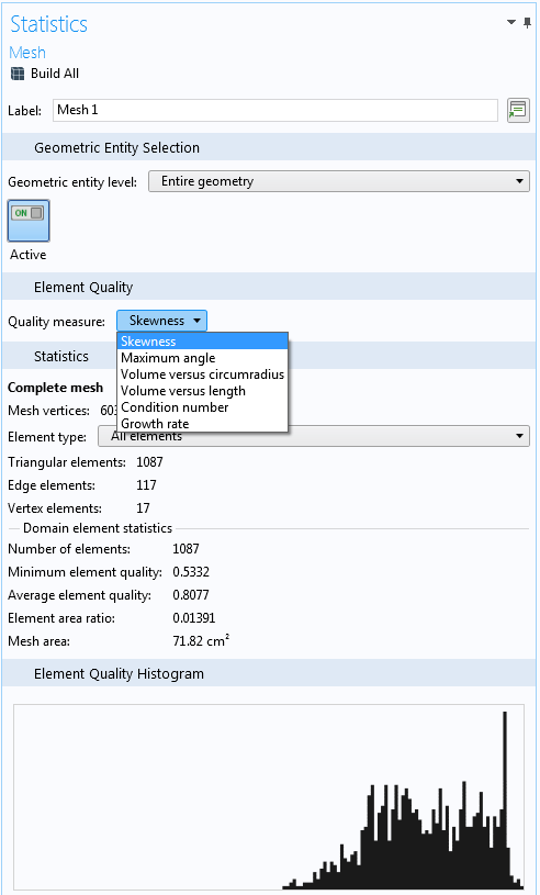
You can now select between several measures of quality for your mesh when they are presented in the Statistics window or a mesh plot. These measures are: Skewness, Maximum angle, Volume versus circumradius, Volume versus length, Condition number, and Growth rate.
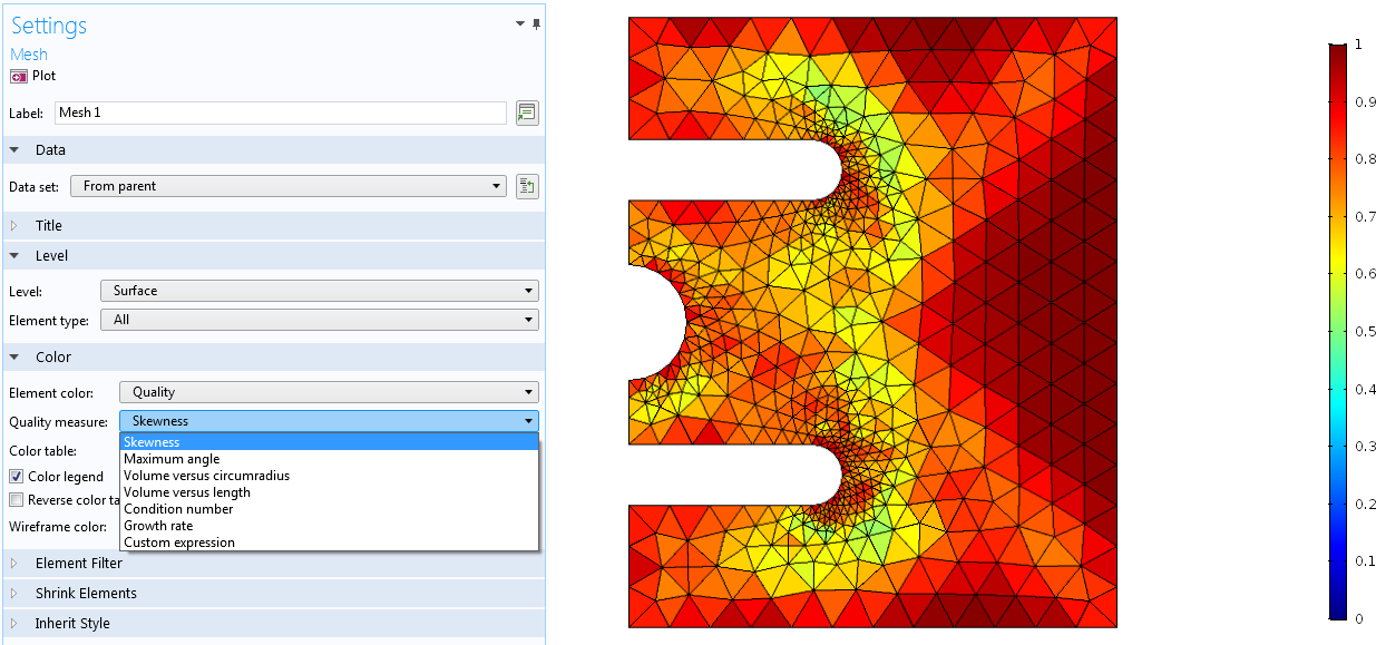 You can choose to plot your mesh quality on your modeling domain by using the following measures: Skewness, Maximum angle, Volume versus circumradius, Volume versus length, Condition number, and Growth rate (left). Here, the growth rate is investigated (right). This evaluates toward a maximum quality measure of 1 in regions of the mesh where the elements are constant in size, while decreasing in regions where the element growth rate increases from one element to the next.
Improved 2D Meshing
The meshing performance for 2D geometries with many domains has improved significantly, mainly through parallelization. Furthermore, the quad meshing operation of domains and planar faces with four right-angled corners now gives more efficient and higher-quality quad meshes.
Automatic Detection of Straight and Planar Edges of Imported Meshes
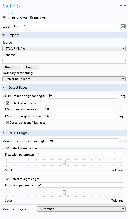
New settings are available in the Import operation for controlling the partitioning of an imported 3D mesh on the edge level. This feature is important when you want to combine the imported mesh with created geometry objects.
Option for Switching Off Mesh Rendering
A new button in the Graphics toolbar enables you to switch off the rendering of the mesh. This makes it easier to see the interior of a 3D object regardless of which part of the geometry has a mesh.

New button in the Graphics toolbar for switching on/off the rendering of the mesh.
Projection Coupling Operators for All Mesh Element Types
The General Projection and Linear Projection coupling operators in the Component Couplings menu of the Definitions node now support all types of mesh elements.
Automatically Remove Geometric Details with Virtual Geometry Operations
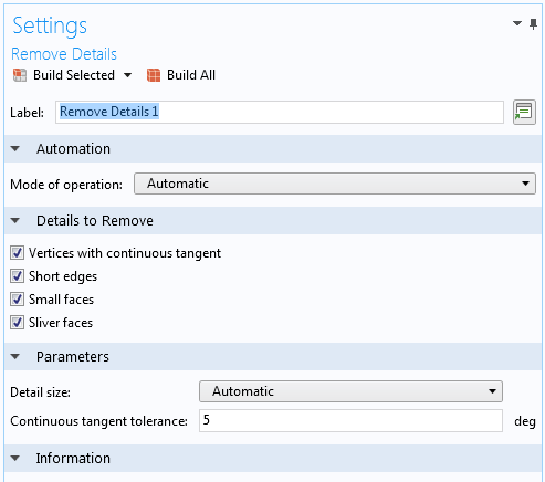
A new 3D geometry operation, Remove Details, has been introduced in order to preprocess your CAD geometries for more successful meshing. This is particularly useful for geometries with small geometric details, which can lead to large meshes of poor quality if they are not handled in a meaningful way.
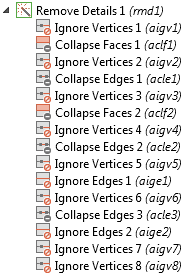
The operation automatically removes short edges and small and sliver (narrow) faces from geometries. The Remove Details operation has two modes: Automatic and Manual. When you remove details in Automatic mode, the operation generates a sequence of virtual operation nodes that you can inspect and edit by switching to Manual mode.
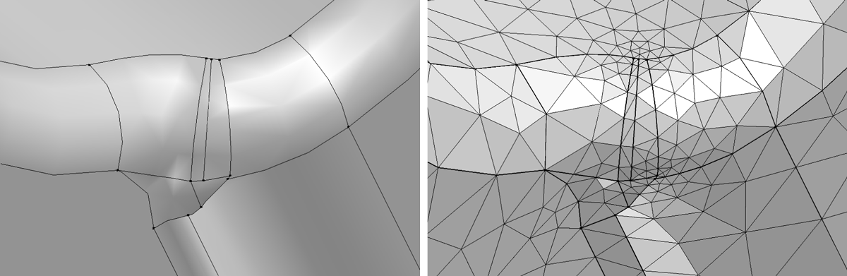 A CAD geometry containing short edges, small faces, and sliver faces (left) results in the corresponding mesh (right).
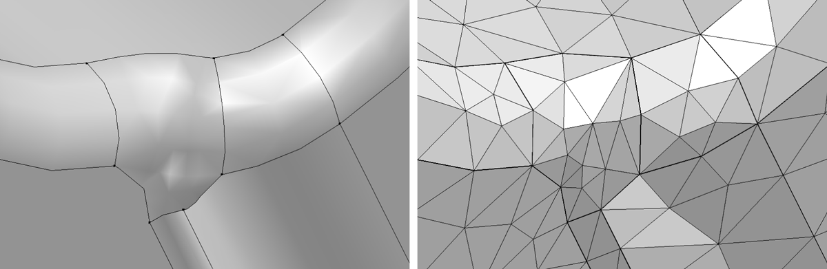
After rebuilding the geometry with the Remove Details operation (left), a much better mesh results (right).
Application Library path for an example using the Remove Details operation:
ECAD_Module/Tutorials/pcb_import