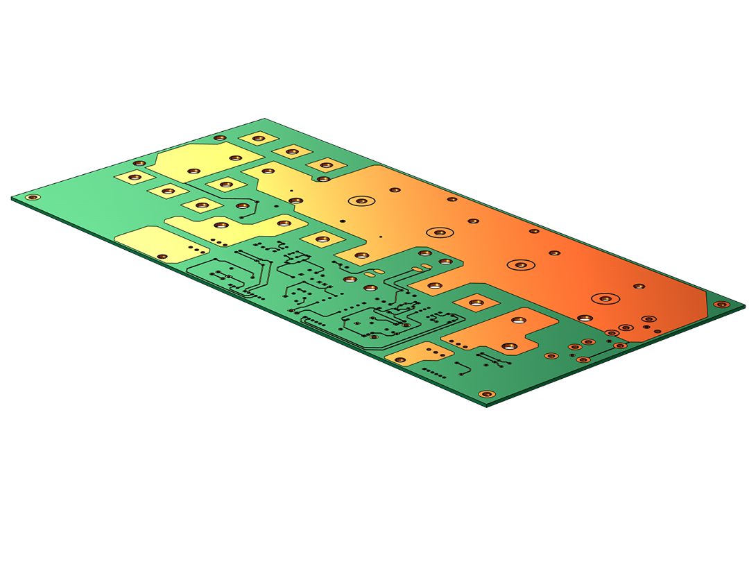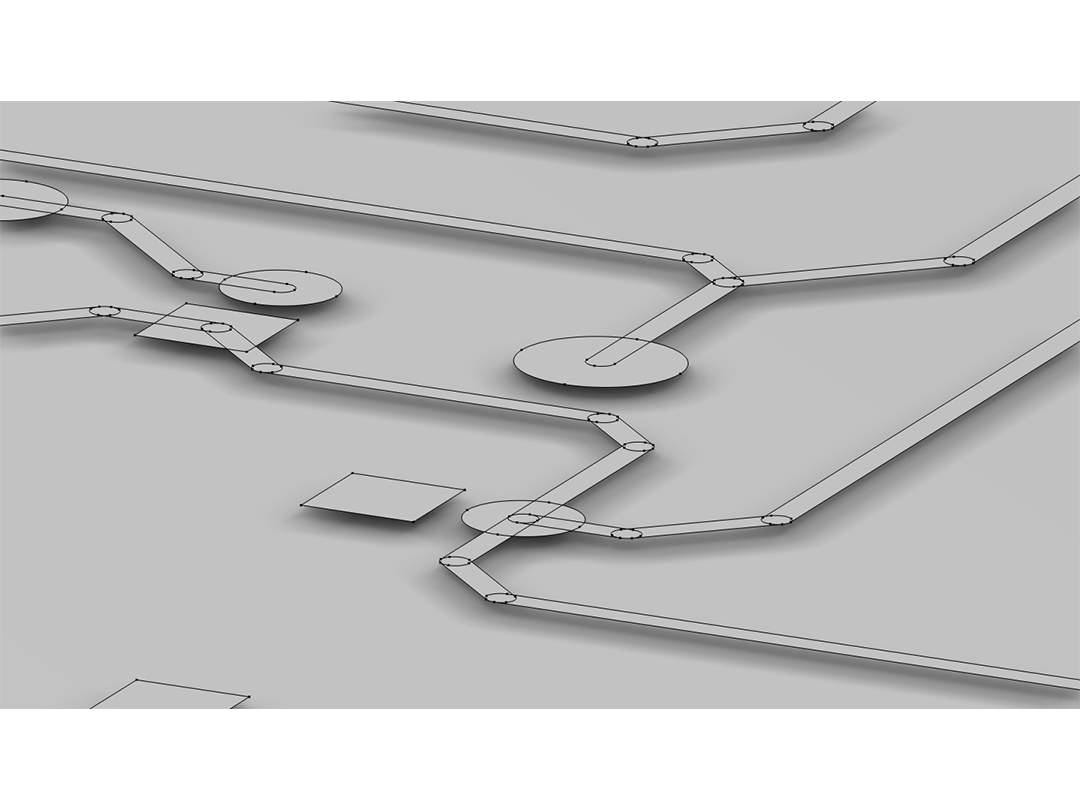
Traitement des fichiers ECAD importés
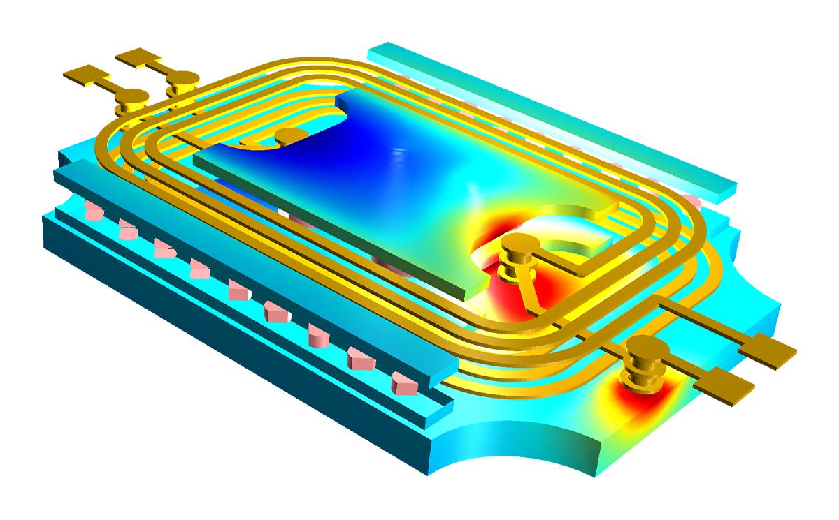
Selon le format du fichier, la fonctionnalité d'import propose différentes options pour configurer la façon d'utiliser les formes géométriques contenues dans les couches des fichiers ECAD importés pour la construction de la géométrie. Les utilisateurs peuvent choisir les couches à importer, modifier les épaisseurs et les hauteurs de ces couches et affiner les paramètres pour simplifier la géométrie. Pour accélérer le processus d'importation, les informations de configuration des couches peuvent être chargées à partir d'un fichier texte. Pour réduire encore davantage le temps consacré au paramétrage des modèles de simulations, l'importation peut être configurée de manière à créer automatiquement des sélections pour chaque couche. Ces sélections sont ensuite disponibles lors de la définition des conditions physiques aux domaines et aux frontières.
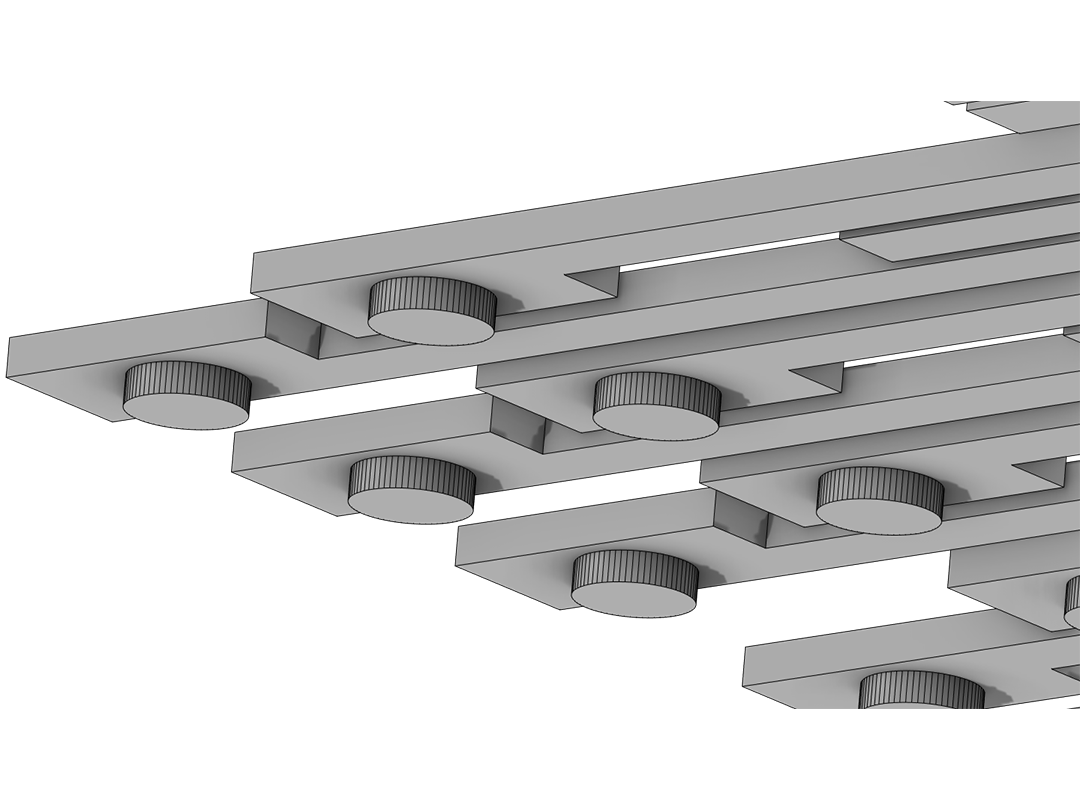
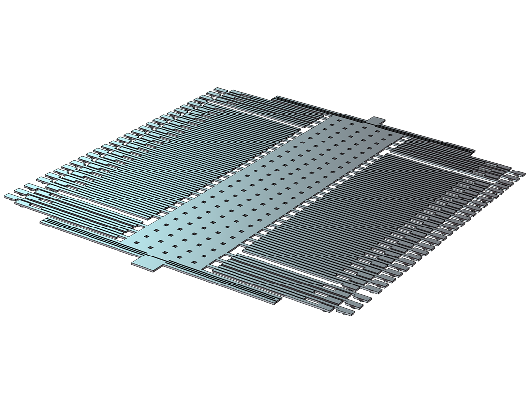
Les objets géométriques 3D construits à partir des schémas ECAD sont représentés dans le logiciel comme n'importe quel autre modèle 3D et peuvent être édités à l'aide des fonctionnalités de modélisation géométrique de COMSOL Multiphysics®.
Lorsque le module ECAD Import est combiné avec le module CAD Import, le module Design ou l'un des produits LiveLink™, la géométrie 3D peut être exportée vers les formats de fichiers IGES, STEP, ACIS® ou Parasolid® pour être utilisée dans d'autres logiciels.