Suite de produits COMSOL
COMSOL Multiphysics® est un logiciel de simulation généraliste utilisé dans tous les domaines de l'ingénierie, de la production et de la recherche scientifique. Le logiciel offre des capacités de modélisation multiphysique et monophysique intégralement couplées, un gestionnaire de modèles et des outils conviviaux pour la création d'applications de simulation. Faites profiter vos équipes de design, vos services de fabrication, vos laboratoires d'essai, vos clients et autres collaborateurs de la valeur de la simulation en distribuant vos applications à l'aide de COMSOL Compiler™ et COMSOL Server™.
Des modules complémentaires fournissent des fonctionnalités spécialisées pour l'électromagnétisme, la mécanique des structures, l'acoustique, les écoulements de fluides, le transfert de chaleur et le génie chimique. Des produits d'interface sont disponibles pour la CAO et d'autres logiciels tiers. Tous les produits complémentaires de la suite de produits se connectent de manière transparente à COMSOL Multiphysics® pour une méthodologie de travail de modélisation unifiée, quel que soit l'objet de la modélisation.
Logiciel multiphysique pour la simulation de designs, de dispositifs et de procédés du monde réel
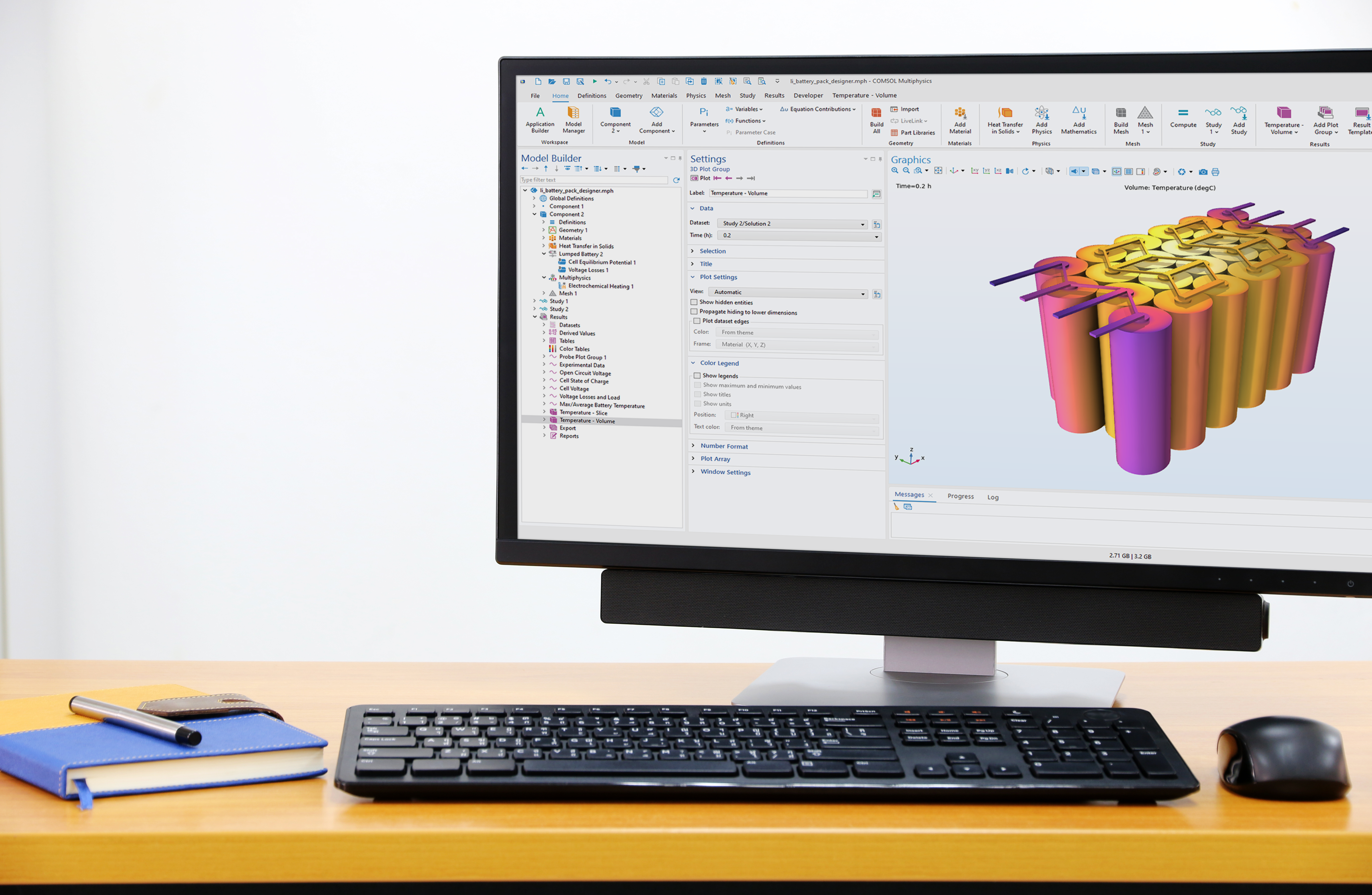
COMSOL Multiphysics®
Tout commence avec COMSOL Multiphysics®, le produit principal pour la création de modèles basés sur la physique et pour la création d'applications de simulation. COMSOL Multiphysics® comprend le Constructeur de modèles, le Constructeur d'applications et le Gestionnaire de modèles. Le Constructeur de modèles contient toutes les fonctionnalités et opérations pour construire, résoudre, visualiser et évaluer les résultats de vos modèles. Le Constructeur d'applications vous donne les outils pour construire vos propres applications de simulation. Le Gestionnaire de modèles est un environnement de travail de gestion des modèles et des applications.